Recovering a Stuck I2C Bus: Distinguish Clock Pulses, Peripheral Reset and Power Cycling
Measure SDA and SCL before choosing recovery. A target holding SDA low may respond to a bounded bus-clear sequence; a line physically clamped low will not. If SCL cannot rise, generating more software clock requests is not a remedy. Resetting the controller, resetting a peripheral, and cycling a power domain affect different state and must be selected from evidence.
Applicability: this guide concerns conventional bidirectional open-drain I2C in Standard-mode, Fast-mode, and Fast-mode Plus. The protocol reference is NXP UM10204 revision 7.0, section 3.1.16. Linux integration examples are checked against v6.12. I3C, Ultra Fast-mode, device-specific timeout protocols, and buffered bus segments require additional review.
1. Capture the fault before disturbing it
Save the controller error, last attempted transaction, power/reset history, and physical SDA/SCL levels. Trigger a logic capture around the first failure where possible. A software timeout alone cannot tell whether the target is absent, the controller is confused, a target is stretching the clock, or the bus has an electrical fault.
Quiesce normal transfers through the owning driver and prevent another task or controller from starting work during recovery. Confirm that legitimate activity has ended and that any permitted clock-stretch interval has been evaluated against the actual device requirements. There is no single timeout value that can be copied safely into every I2C product.
Measure at the relevant segment. A buffer or switch can leave the upstream bus high while a downstream branch remains low. Record supply levels and whether the affected target is powered. Use suitable electrical measurement equipment when logic-level decoding cannot explain rise time or intermediate voltages. A decoder’s label is not a substitute for the waveform.
2. Select recovery from the observed wire state
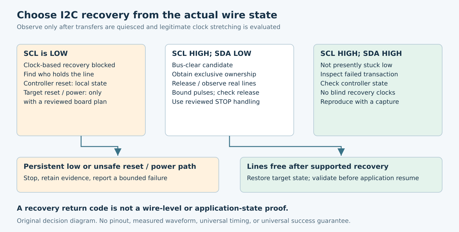
NXP’s bus-clear guidance distinguishes SCL stuck low from SDA stuck low. For SCL stuck low, it prefers hardware reset of devices when available, otherwise power cycling. For SDA stuck low, it describes nine clock pulses, followed by reset or power cycling if the line is not released. This is a bounded recovery recommendation, not a guarantee that pulses cure every fault.
- SCL low: identify the source of the low level after legitimate activity is excluded. Do not drive a push-pull high against a device holding the line. A controller peripheral reset may release its own output, but cannot force an external target to release.
- SCL high, SDA low: consider bus clear only after confirming exclusive ownership and an appropriate device/board recovery contract. Observe actual SCL transitions and SDA release.
- Both high: the bus is not presently stuck low. Inspect controller state, addressing, configuration, and the failed transaction rather than injecting clocks without a reason.
If SDA remains low because of a short or a continuously asserted test clamp, recovery pulses should fail visibly and stop. Repeating them indefinitely obscures the fault and may disturb other devices on the same bus.
3. Review the entire electrical path before GPIO recovery
Inspect the schematic and each relevant datasheet for pull-ups, voltage domains, level shifters, buffers, reset inputs, and power-off pin behavior. Determine whether GPIO control reaches the same physical segment as the hardware controller. Check whether a bus buffer already performs recovery; competing recovery mechanisms can make a capture misleading.
A permitted GPIO recovery path must preserve open-drain behavior: drive low or release, then read back the actual line. Changing pinmux should not create an unintended start, stop, or high drive. Plan how the peripheral driver restores normal pin configuration and internal state afterward, including error exits.
Specify pulse timing from the supported bus/device requirements and count observed clock edges, not merely writes to a register. If SCL fails to rise when released, abort the clock-based path. Do not continue counting fictitious clocks while a target or fault still holds SCL low.
4. Avoid turning recovery into an unintended write
The Linux fault-injection guide describes an interrupted write-byte case in which further clocks can write unwanted data. Its warning matters: a device may still be inside a command, not politely waiting for a fresh address. Recovery needs a reviewed release/STOP strategy, rather than a blind fixed train of clocks.
Prefer the platform’s supported recovery implementation when its capabilities match the board. The Linux v6.12 generic SCL recovery implementation checks whether SCL rises, can generate STOP conditions when SDA is controllable, and checks bus-free state when the necessary observation callback exists. Its behavior depends on the adapter’s supplied recovery hooks.
That implementation can also report success when bus status cannot be checked. Consequently, a successful recovery return is not by itself proof that the actual lines are free or the target’s configuration is intact. Check the adapter implementation and capture the bus before adopting the return code as an acceptance signal.
5. Escalate reset and power actions deliberately
Resetting the host controller addresses its local state machine. Resetting the target can clear a target-side condition, but may also restore configuration registers or affect outputs. Resetting a bus switch might disconnect a branch without resetting the target behind it. Record precisely what each reset line reaches and what must be reinitialized.
Power cycling has wider consequences. Check shared-rail consumers, sequencing, discharge requirements, and whether powered signal pins can back-power the supposedly off device. Use only a board-supported power sequence; disabling a regulator in software is not evidence that the target supply actually fell enough to reset it.
Keep dependent application functions inhibited during recovery. Once the bus is usable, reestablish required configuration and perform a documented, non-destructive health read. Do not replay an interrupted non-idempotent command automatically when its original completion is uncertain. Recovery of communication and recovery of application state are separate checks.
6. Qualify each branch on a safe fixture
For a hypothetical data-acquisition unit, prepare a disposable test setup with controlled fault injection and inactive outputs. Test an incomplete read that releases after clocks, a persistent SDA clamp, a persistent SCL clamp, a target reset, and supported target power cycling. Add a case where the first subsequent transaction fails, so an optimistic bus-free check cannot conceal missing reinitialization.
The acceptance record should identify the fault source, measured initial state, recovery method, observed clocks and STOP behavior, final line state, target configuration, and application result. A persistent clamp must produce a bounded failure and a useful diagnostic. A recoverable interrupted transfer must resume only after the stated validation succeeds.
No bus faults, pulses, or power transitions were executed for this article. The procedure is a proposed decision and test plan. Before deployment, qualify the actual adapter, every affected component, and the board’s reset and power paths. Keep a finite retry policy and preserve the first-failure trace so repeated field faults lead to diagnosis rather than endless recovery loops.