U-Boot FIT Load Addresses: Separate Container Location, Payload Placement and Entry
A FIT image passes the configured verification step, but execution
still fails. The next investigation often starts with the same address
used to load the container. That address is only one part of the boot
contract. The container’s location, the component’s destination and the
eventual entry point can be different values with different owners.
This article follows the main U-Boot v2025.01 bootm path. It does not
generalize that path to every SPL firmware loader or every
operating-system format. For a Buildroot product, use the selected
bootloader configuration, generated FIT and board memory map. No image
was loaded or executed here.
Name the address before
interpreting it
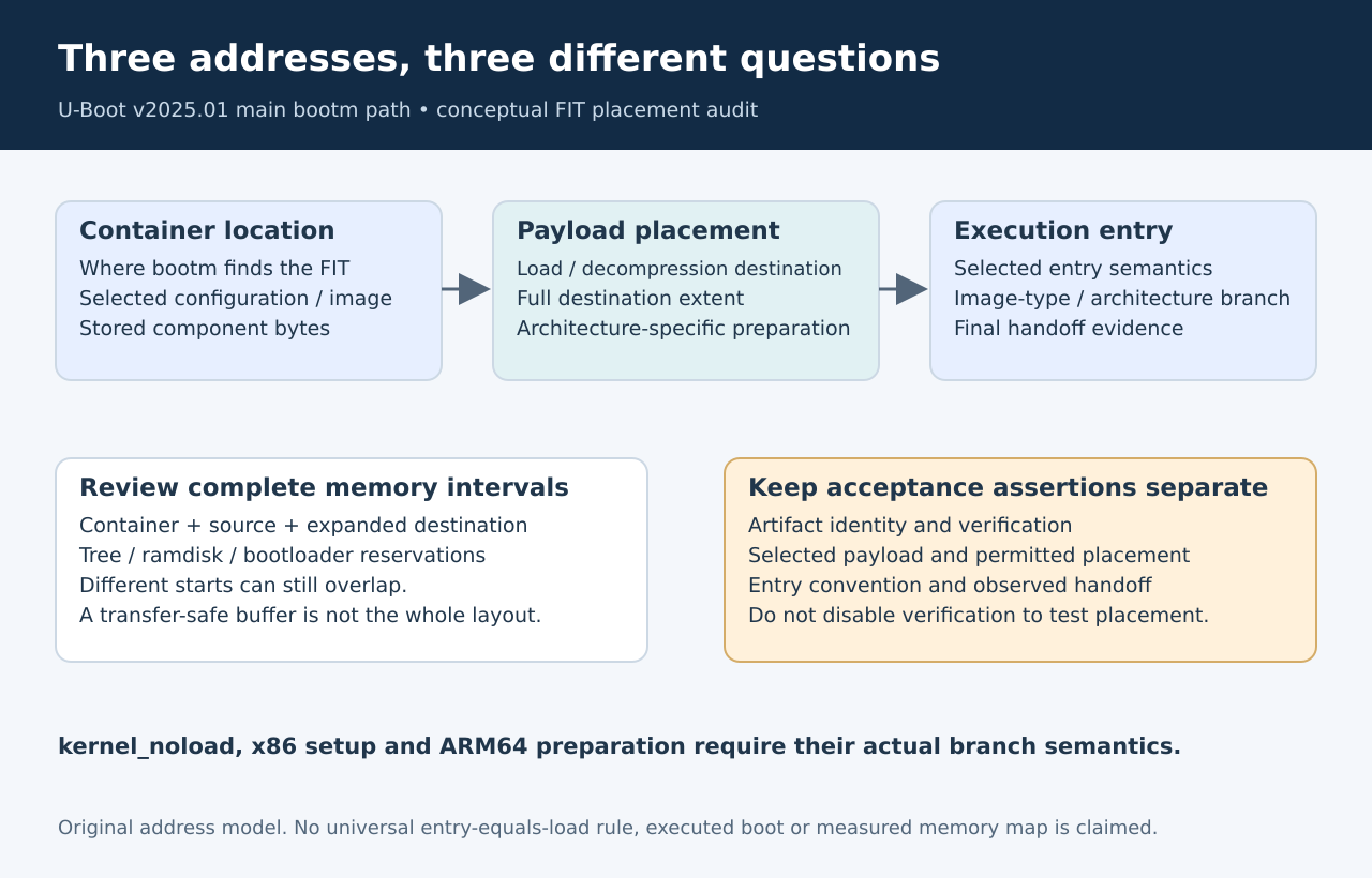
Draw three columns in the release review: where the FIT container
resides in memory, where the selected payload is placed and where
control is expected to enter it. Add the stored payload length and the
expanded or relocated length where applicable. Avoid labeling every
column simply “load address.”
The bootm
command reference accepts a FIT address with an optional
configuration or subimage selector. That argument locates input to the
boot process. The official
single-kernel FIT example separately contains load and entry
properties inside the component description. Its architecture-specific
example values are not a portable board memory layout.
The first practical check is therefore documentary: can the release
owner explain each address without borrowing the meaning of another? A
copied example can produce a syntactically valid container while
preserving placement assumptions from an unrelated platform.
Follow the selected loader
path
In the tagged
bootm implementation, bootm_find_os obtains the selected image’s
properties, including its load address. The entry-point handling has
architecture and image-type branches. The load stage then performs
decompression or placement work and tracks the resulting extent.
This means a generic statement such as “entry always equals load” is
too strong. The tagged code includes special handling for kernel_noload,
x86 setup images and an ARM64 Linux preparation path. Those are reasons
to identify the actual branch before deciding which metadata field
controls the final handoff.
For the product under investigation, record image type, architecture,
operating system and compression together with the selected component.
Then trace only that applicable branch. If a downstream patch modifies
placement or entry handling, include the patch in the evidence. A newer
format specification or a successful boot on another architecture is not
proof of this implementation’s behavior.
Review extents, not
isolated start addresses
A memory review needs intervals. Mark the FIT container’s occupied
region, the source component bytes, the destination or decompression
region and the other boot components. Include the running bootloader’s
reservations and any architecture-specific constraints established by
the payload’s boot protocol.
Two different start addresses can still overlap when an image grows.
A compressed file that fits comfortably in its staging buffer can expand
into a neighboring tree or ramdisk. Record an allowed maximum for the
produced artifact and explain where that maximum is enforced. Merely
repeating the most recent successful image size is not a future-safe
bound.
The tagged load path includes overlap checks and can demand a reset
after detecting an overwritten FIT image. These checks are valuable, but
they do not replace an offline map of the intended layout. They also
make casual target-side address experiments inappropriate on a unit
without a reliable recovery procedure.
Keep transfer bounds distinct from placement bounds. A filesystem
load can safely copy the container into one buffer while a later bootm
operation uses another region for the payload. Correcting the transfer
address without examining the destination can leave the original failure
unchanged.
Separate
authenticity from placement correctness
A valid signature can establish the property it was designed to
establish for the covered data and metadata. It does not demonstrate
that the release’s chosen addresses satisfy the physical board’s
constraints. An authorized but incorrectly configured image remains an
engineering failure.
Do not disable required verification to investigate this problem.
Preserve the signed artifact and inspect its metadata offline. If a
qualification build changes placement, regenerate the artifact through
the approved signing process and record that it is a different test
image. Otherwise, a test can silently switch both the trust policy and
the address layout, making its result difficult to interpret.
The acceptance record should contain separate assertions for artifact
identity, verification outcome, selected component, permitted placement
and observed handoff. Combining them into one “FIT passed” line hides
the exact boundary where the evidence stops.
Qualify the address
contract deliberately
Begin with static inspection of the generated FIT and the payload’s
build outputs. Confirm that the metadata matches the intended
architecture and entry convention. Compare its memory intervals with the
approved board layout using overflow-safe arithmetic and the largest
supported artifact sizes.
Then use recoverable qualification fixtures. Compare the expected
placement with diagnostic evidence from the actual path. Include a
larger valid payload and a deliberately invalid layout only where the
test environment can contain the failure. Record whether rejection
occurs before execution and how recovery is performed; do not assume a
failed overlap test leaves the current session usable.
Finally, repeat the accepted case with the release configuration and
its actual verification policy. The useful outcome is a traceable
relationship from container identity to selected payload, destination
extent and entry behavior. That relationship explains why a verified
image can still fail without confusing a memory-layout defect with a
signature-verification problem.