TinyML FOMO Counting: Check Centroid Collisions Before Changing the Detection Threshold
A camera counter can recognize one component confidently and still count a close pair as one. Before lowering the confidence threshold, ask whether the model’s output can represent both centers separately. A confident answer in one spatial cell does not create a second location inside that cell.
This analysis concerns the MobileNetV2-based FOMO architecture documented by Edge Impulse on October 19, 2026. It does not assume an immutable SDK release or an identical exported model. Record the project version, exported model hash, input and output tensor shapes, and SDK revision before applying the checks below.
Identify the spatial representation
The official FOMO documentation describes centroid training and a class decision at each output cell. Overlapping centroid representations cannot identify separate objects. Its documented default MobileNetV2 cut point reduces each spatial dimension by eight: a 96-by-96 input produces a 12-by-12 map. FOMO does not learn object bounding-box extents; boxes derived from heatmap activations are a compatible output representation.
Treat those facts as an architectural limit to investigate, rather than diagnosing every missed pair as a collision. An occluded object, inconsistent annotation or a weak prediction can produce similar visible symptoms. A box drawn by a viewer also does not establish that the model estimated the object’s physical width.
Map the pair into model coordinates
Use the image presented to the model, after the project’s crop and resize. The C++ inference-function contract says that run_classifier() performs the configured preprocessing and expects the exported impulse’s input length. Sensor-frame coordinates are insufficient when that preprocessing changes the field of view.
For an illustrative 96-by-96 input with an eightfold reduction, use the following simple binning calculation to inspect candidate collisions:
cell_x = floor(input_x / 8)
cell_y = floor(input_y / 8)

centroid A = (18, 42) -> cell (2, 5)
centroid B = (22, 42) -> cell (2, 5)
centroid C = (26, 42) -> cell (3, 5)
The coordinates and divisions are invented diagnostic arithmetic, not inference results or a statement that each neuron sees only an isolated eight-by-eight patch. Check the actual training-label mapping and post-processing in the exported implementation. The useful observation is that A and B compete for one spatial location in this simplified map; A and C do not.
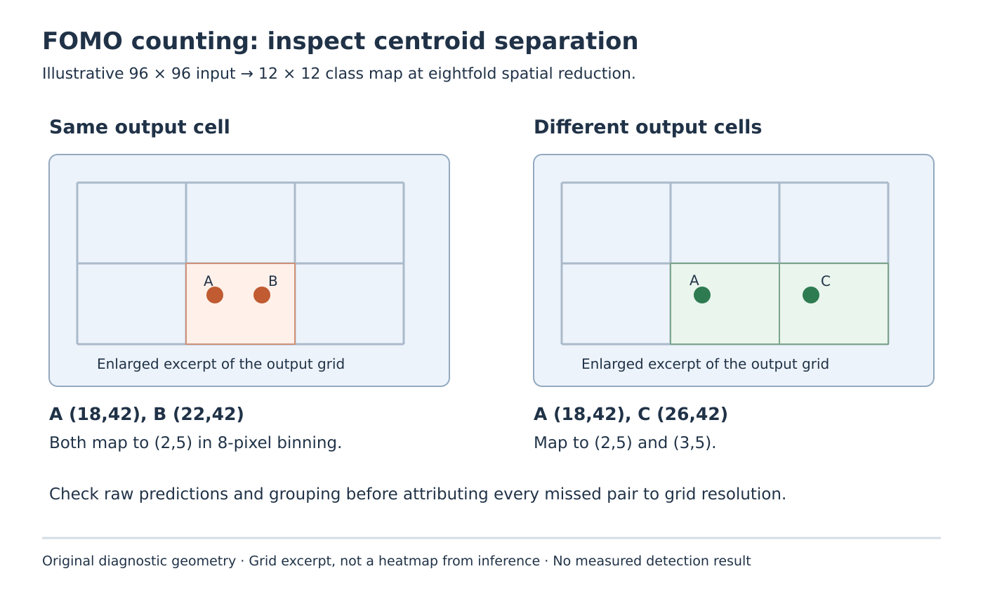
Original geometry diagram. Different occupied cells permit separate locations but do not guarantee two detections.
Build a separation fixture before a threshold sweep
Proposed test: keep illumination, camera pose, exposure settings, object class and acquisition path fixed. Capture one object alone, then a pair whose center spacing is changed in small, recorded steps. Also translate the whole pair across the image while preserving its spacing. Translation helps reveal a result that depends on cell boundaries rather than only on physical distance.
For each frame, preserve the processed input, centroid annotations, raw class map where accessible, threshold and final reported objects. Include both same-class pairs and the class combinations relevant to the application. Record count error separately from localization error: a plausible center for one detection does not make an incorrect count acceptable.
If two distinct candidate regions are visible before the final detection list but only one survives, inspect the export’s thresholding and grouping stage. Do not label that observation a same-cell collision without checking the intermediate representation. Conversely, raising or lowering a threshold cannot add a missing spatial output slot. It changes which existing predictions are accepted.
Choose a change that targets the limiting stage
The documented alternative block_3_expand_relu cut point gives fourfold spatial reduction instead of the default block_6_expand_relu eightfold reduction. Edge Impulse also notes the associated reduction in backbone parameters. A finer map therefore changes the model, not just a display option. FOMO cut-point documentation.
For the illustrative pair, fourfold binning puts x-coordinates 18 and 22 into different columns. That is a reason to evaluate a candidate architecture, not evidence that it will classify either object correctly. Retrain and export the candidate, then repeat the same fixture on the intended microcontroller. Check actual memory fit and execution time instead of assuming that fewer parameters guarantees a smaller complete runtime footprint.
Changing optics, magnification or the region of interest is another experiment if the product can afford a different field of view. Document which scenes then fall outside coverage. Increasing input dimensions needs a matching supported export and integration; changing a camera buffer constant alone is not a model change.
Finish with an acceptance set containing the minimum permitted spacing, expected occlusions, frame-edge cases and empty scenes. Declare the operating envelope from observed results. No model training, camera capture or inference was executed for this article, and no threshold or resolution is presented as a universal counting fix.