RISC-V Trap Vectors: Build mtvec Slots as Instructions Rather Than Handler Addresses
An interrupt-vector table copied from another microcontroller can be completely wrong for standard RISC-V mtvec vectored mode. The hardware jumps to an address within executable code; it does not fetch a handler pointer from that slot.
Build and inspect the vector region according to the selected trap mode. Keep this standard mechanism separate from optional interrupt architectures or vendor-specific vectoring facilities.
Calculate the address the processor will execute
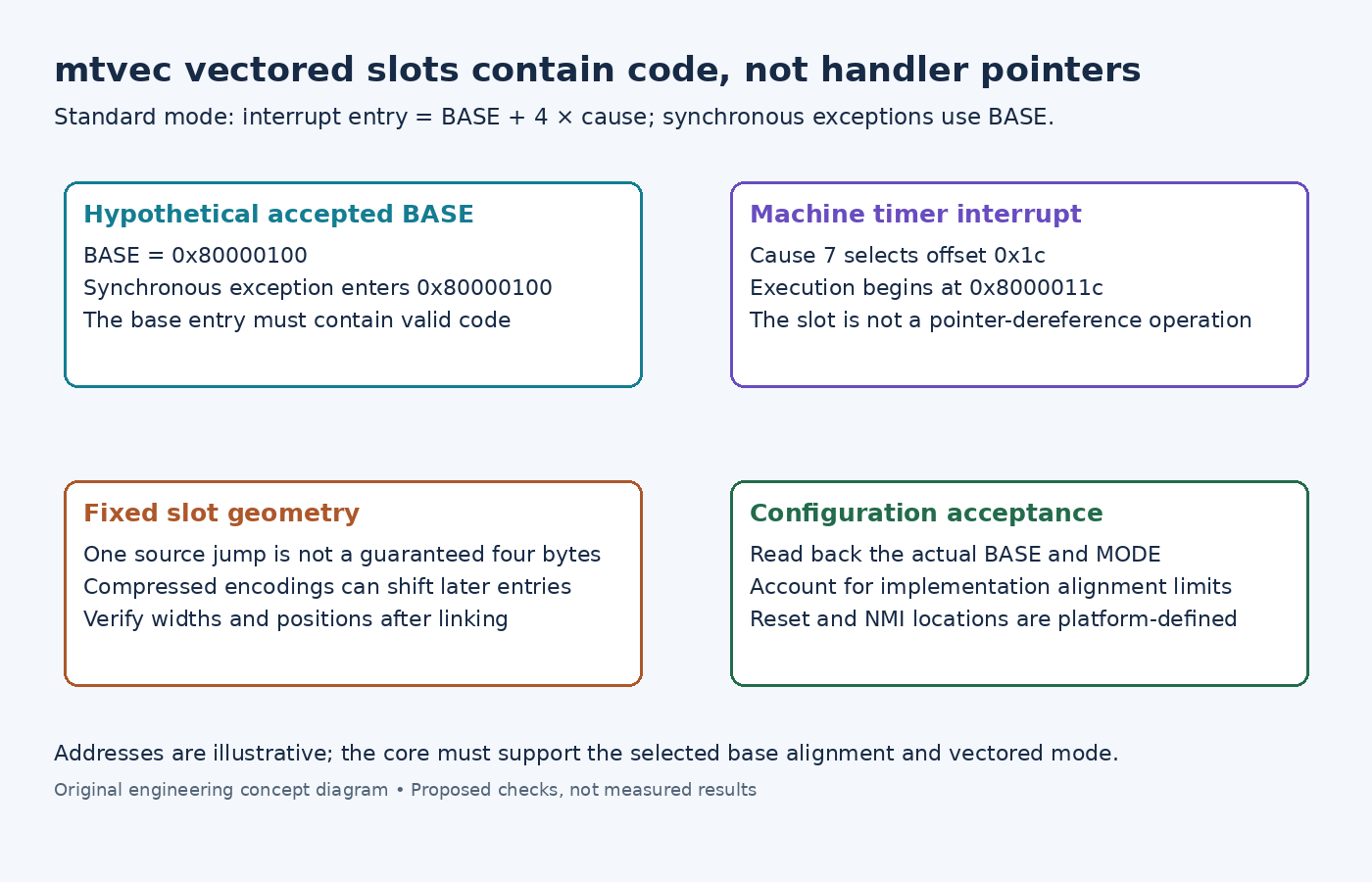
The examined machine-level ISA 1.13 chapter defines two standard mtvec modes. Direct mode sends all machine traps to BASE. Vectored mode sends synchronous exceptions to BASE and asynchronous interrupts to BASE + 4 × cause.
For the standard machine timer interrupt, cause seven selects BASE plus 0x1c. If BASE were 0x80000100 in a suitably supported layout, the processor would begin executing at 0x8000011c. It would not treat the word stored there as a destination address.
Consequently, filling that slot with .word timer_handler supplies address bytes where an instruction is expected. A common implementation instead places a branch or jump instruction in each relevant slot, with larger handler bodies elsewhere. Verify that the chosen instruction reaches its destination and fits the slot.
Preserve four-byte slot geometry
The compressed-instruction specification permits 16-bit instructions intermingled with 32-bit instructions. That does not change standard mtvec's four-byte interrupt stride.
A source containing one jump per line is therefore not sufficient layout evidence. If the assembler chooses two-byte encodings without explicit padding, later entries can occupy the wrong offsets. The hardware still applies four times the interrupt cause.
The official GNU assembler directives document .option norvc to disable compressed instruction generation and .option push/.option pop to scope option changes. Use an appropriate fixed-width assembly policy or explicit slot construction, then inspect the linked bytes. Also audit linker relaxation rather than assuming every source mnemonic retains its original size.
Read back the actual vector configuration
The machine specification defines mtvec as WARL and permits implementations with read-only configuration. BASE requires at least four-byte alignment, while vectored mode may impose stricter alignment. An arbitrary aligned pointer plus mode bit one is not guaranteed to be accepted by every core.
During controlled initialization, write a supported base/mode combination and read it back. Compare the returned BASE and MODE with the intended executable region. Use the processor/platform documentation for additional alignment or fixed-vector restrictions.
Set up the region before enabling interrupts that can reach it. In a multi-hart system, configure each participating hart under its own startup contract. Do not assume one hart's CSR write changes every hart's vector base.
Give synchronous exceptions a valid base entry
A vectored timer handler can work while synchronous exceptions still fail because BASE contains no valid entry code. Preserve a real synchronous-exception path at BASE and dispatch from the captured cause as required. Exception cause numbers are not used as the same offset table in standard vectored mode.
For qualification, inspect the final ELF and disassembly at BASE and the expected interrupt offsets. Propose separate tests for a machine timer interrupt and a deliberately controlled synchronous exception, with recoverable test setup and known handler outcomes. Compare actual entry addresses rather than relying only on a printed handler name.
No vector table was assembled or executed here. The required evidence is an accepted mtvec value plus executable, correctly spaced entries in the actual image. Reset and NMI entry locations remain platform-defined and are not established by this table.