STM32G474 DAC Sawtooth Control: Synchronize Ramp Reset and Step Triggers with HRTIM
A DAC ramp synchronized to an STM32G474 HRTIM cycle needs two event paths: one restores its starting value, and the other advances the ramp. A periodic DAC update trigger alone does not describe that sawtooth sequence. Review the reset event, step event and DAC update limits together before interpreting a waveform.
This article covers a proposed inert DAC1 channel 1 demonstration using G474’s HRTIM v2. The references are RM0440 Rev 9, sections 22.4.11 and 28.3.21, and AN4539 Rev 5, Appendix A.1.2. No power stage, converter stability result or measured ramp is supplied.
Draw reset and step as different wires
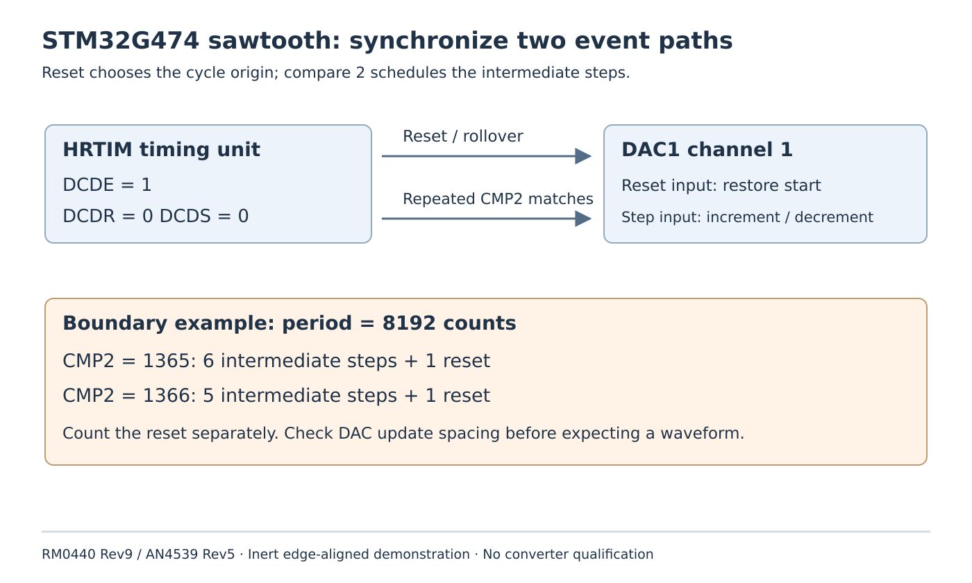
In dual-channel DAC-trigger mode, HRTIM produces hrtim_dac_reset_trgx for reset/update events and hrtim_dac_step_trgx for incremental changes. On the selected timing unit, DCDE enables this feature. The manual forbids changing DCDE while that timer is running with TxEN set.
For the edge-aligned case examined here, choose DCDR = 0 and DCDS = 0. Reset follows counter reset or rollover; step follows compare 2. This avoids importing the different output-set/output-reset timing used by other mode combinations.
The DAC receiver also needs both selections. For DAC1 channel 1, Table 186 maps reset trigger 1 to dac_ch1_trg9 and step trigger 1 to dac_inc_ch1_trg9. DAC_STMODR.STRSTTRIGSEL1 and STINCTRIGSEL1 select the respective paths. Confirm the chosen timing unit’s matching HRTIM trigger output rather than copying a selection from another DAC instance.
Keep ordinary hrtim_dac_trg1 distinct from hrtim_dac_reset_trg1: Table 186 maps the former to DAC1 trigger input 15. Similar names do not identify the same route.
Reserve compare 2 for repeated step generation
With DCDE = 1 and DCDS = 0, HRTIM automatically advances the active compare value after a compare match, producing repeated events separated by the configured CMP2 value. It is therefore more than a single conventional compare instant per period.
Other features that modify CMP2 cannot be enabled indiscriminately alongside it. RM0440 excludes the applicable interleaved, triggered-half and balanced-idle mechanisms for this use. Put that ownership constraint beside the timer allocation so a later waveform feature does not silently take over the step scheduler.
The manual allows changing CMP2 while operating and says the new value takes effect at the next compare match. That is an update boundary to qualify. Do not interpret the software write time as the instant the output ramp has adopted its new step spacing.
Count the rollover event as well as intermediate steps
Table 255 gives a concrete boundary example with TIMxPER = 8192. Dividing the period by six gives approximately 1365.33 counts. The two adjacent integer choices produce different event patterns:
- With
CMP2 = 1365, step events occur at 1365, 2730, 4095, 5460, 6825 and 8190, followed by the reset event at 8192. - With
CMP2 = 1366, five intermediate steps occur at 1366, 2732, 4098, 5464 and 6830, followed by the reset at 8192.
Thus the rounded-up choice gives six events when the reset is included. Calling these “six intermediate steps” would misstate the documented example. The rounded-down choice puts a step only two counter counts before reset, which also makes the DAC’s event-spacing limits important.
Use this as a boundary calculation, not a universal formula for all HRTIM modes. This article does not extend it to centered patterns or prescribe a switching frequency.
Check the DAC’s ability to consume the event pattern
The DAC sawtooth configuration separately supplies its initial value, increment and direction through the documented sawtooth registers. The physical voltage depends on the DAC configuration, reference and output path. Choose conservative illustrative values from the selected channel’s limits instead of assuming a timer count directly represents millivolts.
Section 22.4.11 makes reset higher priority than increment and limits trigger rate by the DAC data-update capability. Too-fast increment events can be ignored; a reset arriving in the stated update interval can be held until after the increment. An HRTIM event schedule alone therefore does not establish the exact analog shape.
For a proposed bench fixture, keep power-stage outputs disconnected, select a legal low-rate timing configuration, and observe the available DAC output using suitable loading and instrumentation. Compare rollover alignment, number of visible steps and the transition after a deliberate CMP2 update. Record register configuration separately from observations.
The review is complete when the selected timer owns both event paths, the DAC receives the intended reset/step pair, conflicting compare modes are excluded, and the event spacing satisfies DAC limits. Control-loop behavior and protection qualification remain separate engineering work; none was tested here.