STM32G474 Multiple FDCAN Controllers: Set the Shared Divider Before Per-Instance Timing
Initializing a second STM32G474 FDCAN controller can disturb the first controller’s bit timing if the initialization also changes the shared input-clock divider. The timing registers are per instance, but FDCAN_CKDIV is a global dependency exposed through FDCAN1.
Give the divider one startup owner and finish that configuration before setting up the other controllers. The source is RM0440 Rev 9, section 44.4.37. This article examines a hypothetical two-controller G474 integration. It does not assert a CubeMX or HAL defect, and no CAN interface or bus was exercised.
Put the shared register above the per-instance drivers
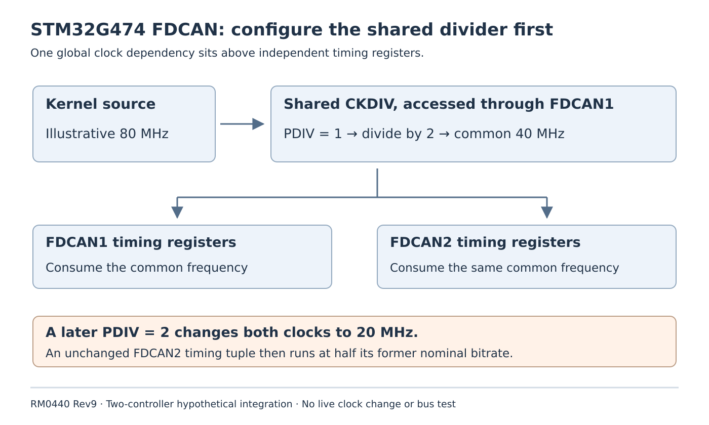
RM0440 states that only FDCAN1 has the clock-divider register, that the divider affects all FDCAN instances and that it must be modified before configuring the other instances. The bitrate calculation uses the divider output clock.
This makes the initialization dependency different from two wholly independent peripherals. A board-level configuration routine should establish the common kernel source and divider contract. Each per-instance driver can then derive its timing from the resulting frequency without independently rewriting the shared divider.
Access through FDCAN1 does not mean FDCAN1 must transmit frames for FDCAN2 to operate. The requirement concerns the shared register’s location and configuration order. Keep that distinction clear when an application uses only the second controller for traffic.
The divider field is write-protected and requires the documented configuration-change enable condition. Use the complete peripheral initialization procedure rather than treating it as an ordinary live clock-control register.
Decode PDIV before calculating the common frequency
The four-bit PDIV encoding is not the literal divider. The manual maps zero to divide-by-one, one to divide-by-two, two to divide-by-four, three to divide-by-six and so on through fifteen to divide-by-thirty.
For an illustrative kernel source of 80 MHz, PDIV = 1 produces 40 MHz for the FDCAN subsystem. Both controller timing plans must use that output. A configuration field labelled simply “divider 2” is ambiguous until the team establishes whether it means raw encoding two or effective division by two.
Record the encoded field and decoded divisor separately. Apply the same distinction to each controller’s own timing fields; a raw register value and an effective time-quantum count are different representations.
The 80 MHz assumption is arithmetic for this example. Verify the actual selected source, permitted device limits and board tolerance for a real design. A comment copied from another board is insufficient clock evidence.
Reconstruct an order-dependent failure
Suppose the board owner establishes PDIV = 1, so the common timing clock is 40 MHz. FDCAN2 is then configured with an effective nominal prescaler of five and sixteen total time quanta per bit. Under those illustrative values, its nominal rate is 500 kbit/s.
Later, an independent FDCAN1 initialization path writes PDIV = 2, producing division by four and a 20 MHz common clock. FDCAN2’s own timing registers are unchanged, but the same timing tuple now corresponds to 250 kbit/s.
This is a dependency failure: reviewing only FDCAN2’s register dump can miss the changed input. The example demonstrates the consequence of a prohibited initialization arrangement; it is not a recommendation to change the divider while another controller is active.
A useful software review searches every write to CKDIV, including generated startup, driver reinitialization and recovery helpers. Identify which one is allowed to establish the global setting and which callers should merely consume it. Do not diagnose a vendor-library bug from an old forum example without checking the exact deployed source.
Make controller order irrelevant after common setup
Write the startup sequence as three explicit phases: establish the shared clock/divider under the documented prerequisites; configure each controller’s nominal and applicable data-phase timing from that frequency; then enable their intended operation through the supported driver paths.
After the first phase, ordinary per-instance initialization should not silently alter the shared frequency. If two clients request incompatible global settings, report that conflict to the board-level owner instead of allowing the last initializer to win.
Recovery deserves the same review. A routine that reconfigures one instance must account for every other user of the shared divider. A genuine global-clock change needs a coordinated transition and regenerated timing for the affected instances; this article supplies no live reconfiguration procedure.
Qualify the dependency before testing the network
A proposed software fixture records the common divider and each timing plan after every initialization call. Try both per-instance initialization orders after the same common setup, and include a repeat initialization of one controller. The expected invariant is a stable shared divider and unchanged timing assumptions for the other instance.
On an isolated CAN bench, subsequently verify actual waveform timing and error behavior with the selected transceivers and network. Keep that physical qualification distinct from proving that startup owns the global register correctly.
The handoff artifact is a short ownership trace: who configured the shared divider, its encoded and effective values, which instances consume its output and which reinitialization paths preserve it. That resolves an order-sensitive multi-controller integration problem before a misleading per-instance timing adjustment hides it.