Gateway Power Rails: Use Enable Hysteresis to Avoid a Cable-Drop Restart Loop
A gateway can repeatedly start and stop even when its remote supply stays at a steady voltage. Turning the converter on increases cable current, the local input falls below its stop threshold, and shutdown removes the load. The local voltage then recovers above the start threshold and repeats the cycle. The supply display can look normal because the oscillation is created at the receiving end.
This article examines that low-voltage state-transition problem, not input-filter resonance or source current limiting. Texas Instruments’ TPS62125 datasheet, SLVSAQ5E, revised May 2017, section 8.2.2.2 on pages 14–15, supplies a concrete example of independently adjustable enable thresholds. The cable and load calculations are hypothetical, not a validated gateway design.
Draw the two operating points
Start with a simple resistive supply model: local input equals remote source voltage minus input current multiplied by total loop resistance. Include both conductors and relevant connectors. This model omits cable inductance, source dynamics, and converter input capacitance, so it describes steady operating points rather than every transient.
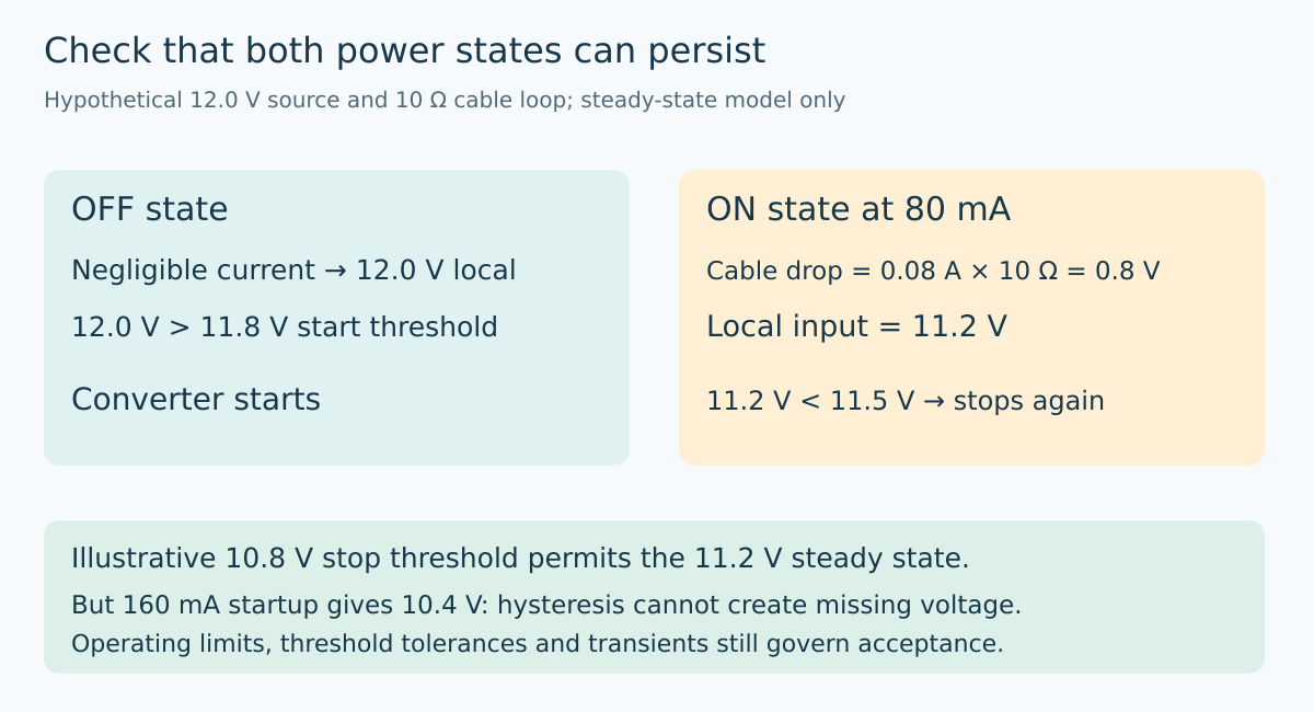
Assume a 12.0 V remote source and 10 Ω total loop resistance. With the converter disabled, neglect its small residual current and the local input is approximately 12.0 V. With an assumed 80 mA operating input current, local input becomes 11.2 V.
Now choose an 11.8 V start threshold and an 11.5 V stop threshold. The unloaded rail is high enough to start, but the loaded rail is below the stop threshold. Neither state can persist: off causes another start, and on causes another stop. Filtering the enable signal may change the repetition interval without removing this inconsistency.
Give the on state enough room to exist
If the stop threshold were 10.8 V instead, the illustrative 11.2 V loaded input could remain above it. The 1.0 V threshold separation would accommodate the assumed 0.8 V resistive drop, leaving 0.2 V before other uncertainties. That small remaining margin is a warning, not a finished design.
The lower threshold must still be above whatever boundary is necessary for correct operation. Suppose the system independently requires at least 10.5 V at the converter input for its supported behavior. A nominal 10.8 V stop threshold might be compatible, but only after threshold error, resistor tolerances, input ripple, and transient undershoot are accounted for.
Hysteresis cannot create missing voltage. If a required startup interval draws a hypothetical 160 mA through the same loop, the resistive estimate becomes 10.4 V. That is below both the proposed stop threshold and the assumed required operating voltage. Wider hysteresis alone would merely allow the circuit to run in an unsupported region.
Translate thresholds into the actual enable circuit
TPS62125 uses an enable comparator and an additional hysteresis connection. Its published equations use a nominal 1.2 V rising comparator threshold and 1.15 V falling threshold, together with three resistors. The resistor network sets input-referred start and stop voltages; it is not equivalent to choosing a generic GPIO’s logic thresholds.
For an illustrative calculation, let the lower start-divider resistor be 100 kΩ. A nominal 11.8 V start target gives an upper resistor of approximately 883.33 kΩ from 100 kΩ × (11.8 / 1.2 − 1). Substituting that value and a 10.8 V stop target into the datasheet’s separate stop equation gives approximately 5.27 kΩ for the hysteresis resistor.
These are algebraic results, not a recommended bill of materials. Real values must be selected from available components, then the thresholds recalculated at the documented comparator and resistor corners. Check enable-pin conditions and the datasheet’s divider-current guidance. Do not assume nominal resistor rounding is the only error source.
Use the current the converter actually draws
The constant 80 mA example makes the state logic easy to inspect. A real regulated converter’s input current depends on output power, efficiency, and local input voltage. As local voltage falls, the current needed to maintain a fixed output power can rise. The cable drop and current therefore interact.
For a more complete steady-state model, solve the load and cable equations together using appropriate converter efficiency information. For startup, include charging current and the sequence in which downstream loads become active. Do not substitute the output current directly into a cable-drop equation for the converter input.
Also distinguish a resistive-drop loop from a source that enters current limit or timed retry. If the remote source itself collapses first, changing the converter’s enable divider may not address the dominant failure. Capture both ends before naming the mechanism.
Observe the enable decision directly
On a current-limited low-voltage bench setup, capture remote source voltage, local input voltage, enable state, and output voltage. If accessible, add input current. Trigger on the enable transition and retain enough time to include multiple attempts or a successful stable start.
The hypothesized loop predicts a particular order: enable rises, load current increases, local input crosses the stop level, enable falls, and local input recovers. If the order differs, revise the explanation rather than fitting every restart to a hysteresis story.
Repeat with the supported cable extremes, connector conditions, load sequences, and input-voltage range. Account for measurement uncertainty when comparing a waveform with a threshold. A threshold inferred from one noisy transition is not a guaranteed comparator limit.
Define recovery without promising impossible startup
Document the source voltage at which startup is permitted, the lowest sustained operating input, and the conditions requiring shutdown. A deliberate refusal to start can be preferable to repeated partial boots that corrupt peripheral state or conceal inadequate supply margin.
Where startup demand is the issue, consider supported sequencing, reduced startup load, or a lower-loss supply path. Each changes a physical cause. A time delay or enlarged hysteresis band is useful only when it establishes a valid operating state within all component and load requirements.
The final evidence should show stable on and off states, toleranced thresholds, and bounded transitions between them. Hysteresis is not a cosmetic anti-chatter setting. Properly designed, it expresses the voltage room that the gateway needs when switching from an unloaded cable to a working system.
Topic provenance
The preserved Google Trends RISING row “industrial iot solutions,+110%,” worldwide, all categories, web search, July 19–October 19, 2026 supports the parent integration topic only. It does not establish search growth for this electrical mechanism or article title.