Modbus RTU to MQTT: Register Mapping, Byte Order and Scaling
A reliable Modbus RTU to MQTT integration needs an explicit contract between a device register map and the application consuming its measurements. A successful serial reply proves that bytes arrived. Commissioning must also establish what those bytes mean and whether the resulting value is still current.
This guide covers read-only telemetry: address conversion, function codes, signed values, scaling, multi-register order and MQTT freshness. All register assignments, values and payloads below are illustrative, not Obeita product specifications or field measurements.
Start with one proven RTU read
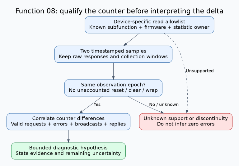
Gather the device model, firmware revision, register-map revision, serial settings, station address and a known reference value. Confirm the RS-485 wiring, termination and biasing against the installation documentation. Ensure only the intended master controls the bus. Resolve timeouts and CRC failures before attempting to correct values with scaling.
The Modbus serial-line guide defines RTU framing, timing and error checking. A production poller must respect those requirements as well as device response limits. Start with one documented point; expand the poll set only after its raw response and decoded value agree.
Resolve the register address and function code together
The Modbus application specification uses zero-based PDU addresses. Function code 03 reads holding registers; function code 04 reads input registers. These are distinct logical tables. The same numeric offset does not establish that the two functions return the same measurement.
In conventional documentation notation, 40001 identifies the first holding register and 30001 the first input register. The leading digit identifies the table; it is not part of the transmitted PDU address. See the Modbus Organization’s addressing explanation.
| Illustrative manual entry | Function | PDU start address |
|---|---|---|
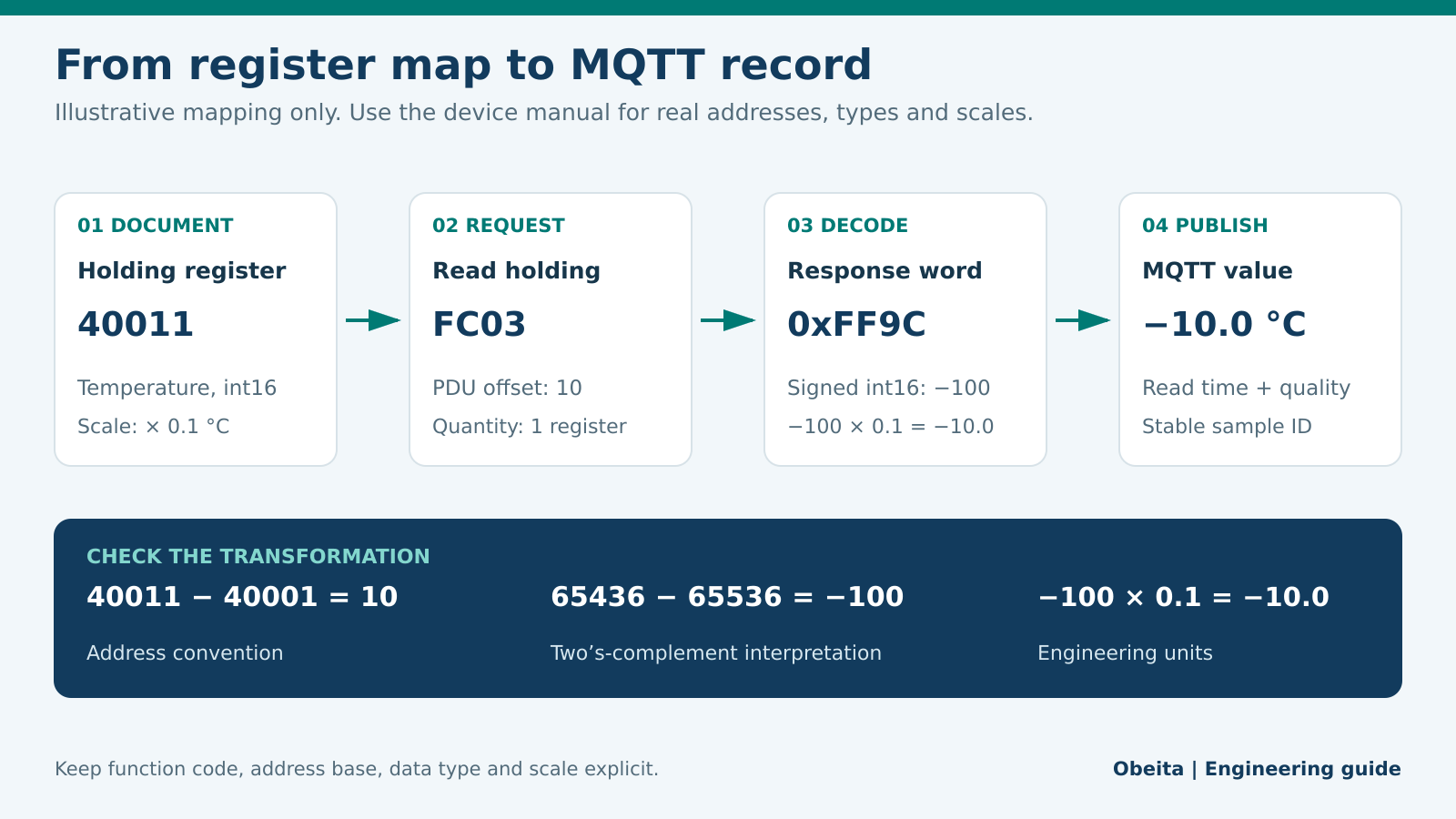
| Holding register 40011 | 03 | 10 decimal, 0x000A |
| Input register 30011 | 04 | 10 decimal, 0x000A |
For that convention, 40011 − 40001 = 10. However, manuals may already provide zero-based offsets, one-based register numbers or hexadecimal addresses. Gateway interfaces can apply their own conversion. Record both the manual notation and the actual PDU offset; never subtract one automatically. Do not replace FC03 with FC04 to obtain a plausible number unless the device documentation explicitly supports that mapping.
For the first example, the request PDU is 03 00 0A 00 01: function 03, start 10, quantity one. This is a PDU only, not a complete RTU frame; the station address and CRC are omitted.
Decode signed values before applying scaling
Build a point definition containing station address, function, PDU offset, register count, data type, word order, scale, offset, unit, invalid-value rules and freshness limit. Preserve the raw register words in commissioning logs so another engineer can reproduce the conversion.
Suppose the illustrative point is a signed 16-bit temperature with a scale of 0.1 °C and zero offset. A response word of 0xFF9C is 65436 when read as unsigned. Its signed two’s-complement interpretation is 65436 − 65536 = −100. Apply scaling after decoding:
engineering_value = decoded_value × scale + offset
                  = -100 × 0.1 + 0
                  = -10.0 °C
An unsigned decoder would instead publish 6543.6 °C. Changing the scale to hide that result would leave the underlying type error intact. Test positive, negative and boundary values. Check manufacturer-defined invalid codes before scaling; a sentinel must not become a believable measurement.
Separate 16-bit byte order from multi-register word order
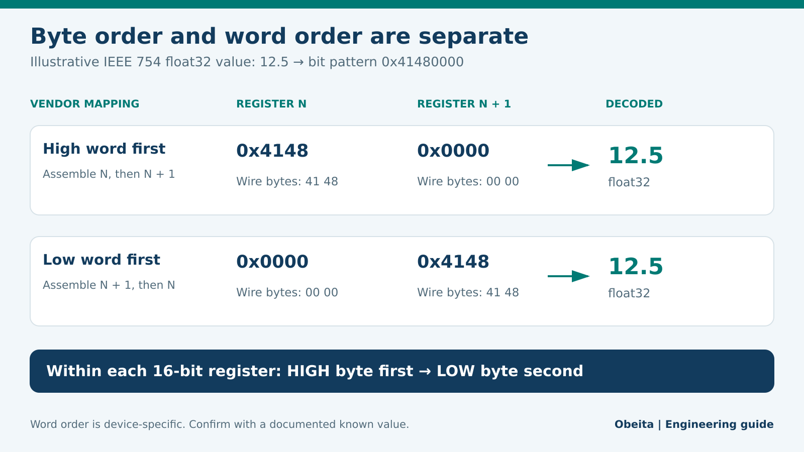
Within a standard 16-bit Modbus register, the high byte is transmitted first. Thus 0x4148 appears as 41 48. The RTU CRC is a separate field whose low byte is sent first; its order is not a rule for register decoding.
A 32-bit application value occupies two registers, but its word arrangement is device-specific. Schneider Electric’s swapped-floating-point example demonstrates why the most- and least-significant words sometimes require reordering.
For an exact illustrative IEEE 754 float32 value of 12.5, the bit pattern is 0x41480000. A high-word-first map returns 0x4148, 0x0000; a low-word-first map returns 0x0000, 0x4148. Reorder the words according to the manual, then reinterpret the assembled bits as float32. Numerically converting the assembled integer to a floating-point number is a different operation.
A gateway option called “little endian” can be ambiguous. Document the exact word and byte permutation it applies. Some vendor mappings also define application-byte swaps; verify those explicitly. Read related words in one request where supported, and check whether the device guarantees a coherent snapshot during updates.
Publish freshness and quality with the MQTT value
Give each measurement a stable point name, unit, quality state and timestamp with a stated meaning. If the device provides no acquisition timestamp, label the gateway’s successful read time honestly. A later publication time must not disguise an old sample.
This illustrative application payload uses gateway read completion time and a boot-scoped sequence:
{
  "schema_version": 1,
  "device_id": "example-device-07",
  "point": "temperature",
  "value": -10.0,
  "unit": "degC",
  "quality": "good",
  "read_completed_at": "2026-10-03T12:00:00Z",
  "time_source": "gateway_read",
  "boot_id": "example-boot-01",
  "sequence": 1042
}
Define what happens after a missed poll: for example, preserve the last-good timestamp while reporting stale quality, or publish an explicit unavailable value. Specify a stale threshold suitable for the process, clock synchronization expectations and queue limits. When replaying buffered samples, preserve their original read times.
Retained MQTT messages can help a new subscriber obtain the last published state, but retention does not establish freshness. MQTT 5 Message Expiry can limit queued-message lifetime; consumers still need application-level age checks. See MQTT 5.0 sections 3.3 and 4.3.
Choose QoS without promising end-to-end exactly-once processing
MQTT QoS 0 provides at-most-once delivery, QoS 1 at-least-once delivery, and QoS 2 exactly-once delivery within its protocol exchange. The specification scopes delivery to a single sender and receiver; broker-to-subscriber delivery is a separate exchange. QoS 2 alone cannot guarantee exactly one sensor acquisition or database update across the entire system.
Design consumer writes to be idempotent when duplicates matter. An application key combining device, boot ID and sequence can support deduplication if its uniqueness and persistence rules are defined. Test reconnects and downstream retries with the actual broker, client and storage configuration.
Commissioning checklist
- Compare the request PDU with the approved address map, including FC03 versus FC04.
- Verify raw words against a known device indication before enabling cloud calculations.
- Exercise negative values, invalid codes, word-order changes and partially failed polls.
- Disconnect the serial device and broker separately; confirm stale data stays identifiable.
- Restart the gateway and consumer; check replay age, duplicate handling and sequence behavior.
- Record the tested firmware, map revision, payload schema and acceptance results.
Prepare a Modbus RTU to MQTT requirements review
For an Obeita integration discussion, prepare the relevant device-manual pages, a sample request/response frame, expected engineering values, point count, polling interval, broker requirements and outage behavior. Redact passwords, keys, customer identifiers, private network details and proprietary data you are not authorized to share. Those inputs make it possible to define and test the mapping before committing to a gateway configuration.
Explore Obeita’s legacy device connectivity service and the delivered STM32 data acquisition and MQTT integration project for related engineering scope. To discuss your own mapping requirements, contact Obeita.
Primary references
- Modbus Application Protocol Specification V1.1b3. Relevant sections: 4.2, 4.3, 4.4, 6.3, 6.4.
- Introduction to Modbus — Modbus Organization. Relevant sections: Modbus data addressing and function 03.
- Modbus over Serial Line Specification and Implementation Guide V1.02. Relevant sections: 2.2, 2.5.1, 3.
- Schneider Electric — How to read swapped floating point values in Modbus. Relevant sections: Resolution.
- MQTT Version 5.0 — OASIS Standard. Relevant sections: 3.3.1.3, 3.3.2.3.3, 4.3.