An RTC Alarm Fires but the Product Stays Asleep: Trace the Wake Path End to End
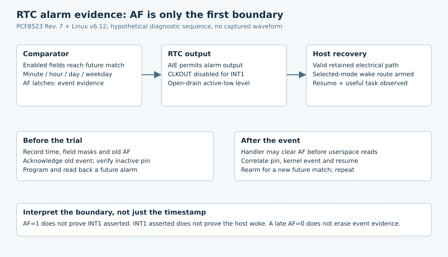
Separate an RTC alarm match from an asserted interrupt pin and a successful host wake. On the NXP PCF8523, a latched alarm flag can coexist with disabled alarm output or a pin still configured as CLKOUT. A later read showing that time passed the alarm is not evidence that the sleeping host received a usable wake signal.
Applicability: this diagnostic example pins PCF8523 data sheet Rev. 7, 28 April 2015, and Linux v6.12 rtc-pcf8523.c. It is for existing designs: NXP currently lists PCF8523 as no longer manufactured. The fixture is hypothetical, and no alarm or suspend test was performed. Other RTCs have different flag and output rules.
1. Identify the actual alarm source
Map the board’s RTC component to its Linux rtcN device and interrupt wiring. Do not assume rtc0 is the battery-backed component that controls wake. The Linux RTC guide explains that systems can have multiple RTCs and that not every RTC has an IRQ connection.
Record the exact package and connected output from the schematic. Identify the interrupt pull-up supply, any translator or inverter, the host input, and the retained wake-controller route. Keep the normal I2C access path separate: reading the RTC while the host runs does not validate the interrupt path during sleep.
Give the test an independent recovery method and an observation window long enough to distinguish a missing wake from a scheduling mistake. Preserve unrelated alarm users and system time-management policy; do not overwrite a production alarm owned by another service.
2. Establish the comparator result before blaming routing
The Rev. 7 alarm description compares enabled minute, hour, day, and weekday fields. AEN_x=1 excludes that field. All enabled comparisons must match, and AF latches when the match first occurs. There is no seconds alarm field.
For a hypothetical fixture, choose a future minute boundary far enough away to finish programming and enter the intended sleep mode. Record the RTC’s own current time, requested alarm, effective field enables, and readback. Do not judge success against an unverified host wall clock or assume a request for an arbitrary second can be represented exactly.
The v6.12 driver advertises minute alarm resolution. Its read-alarm path reports seconds as zero, enabled from AIE, and pending from AF. These are three distinct observations, not interchangeable definitions of a successful wake.
First qualify a running-system case. If the expected comparator event is absent, inspect time validity, the actual alarm fields, masks, and programming errors. Do not move directly to interrupt-controller settings while the source itself remains unproven.
3. Check AF, AIE, and CLKOUT independently
PCF8523 alarm output requires AIE, while AF remains latched until cleared through the interface. The shared INT1/CLKOUT pin requires CLKOUT to be disabled for INT1 use. Its interrupt output is active low and open drain; an asserted alarm is a level, not a programmable alarm pulse.
Build a small evidence row with AF, AIE, CLKOUT selection, and the measured pin condition. An AF=1, AIE=0 case demonstrates an alarm event without enabled alarm output. An AF=1, AIE=1 case still requires checking the pin function and electrical path.
The driver configures the clock-output control when a usable client IRQ is present. Nevertheless, inspect the tested build and effective configuration. A firmware modification, alternate driver, or later register write can invalidate an assumption based only on probe source.
Do not infer a valid inactive high merely because an open-drain output is released. The pull-up rail must remain available, and its voltage must satisfy both components’ limits through the selected sleep state. Choose resistance from the actual load, timing, and leakage constraints rather than using a universal RTC pull-up value.
4. Preserve evidence before acknowledging it
AF clearing has device-specific write semantics. The data sheet’s Control_2 example clears AF by writing zero while preserving other required fields and flags appropriately. Do not transplant a write-one-to-clear pattern from another peripheral or write an unreviewed constant across the register.
In v6.12, the driver’s threaded handler reads Control_2, attempts to clear AF, and reports an RTC alarm event. A userspace pending read after that handling can therefore be clear even though the event occurred. Capture kernel event evidence and the physical pin alongside late status reads.
Conversely, a stale AF from an earlier event can keep the alarm condition visible. Before a new trial, record and acknowledge old evidence through the owning driver or a controlled diagnostic implementation, then verify the inactive condition. Avoid direct register access racing a bound production driver.
Clearing AF does not continuously retrigger it during the same matching time. Nordic-style GPIO level rearming assumptions do not apply here; follow this RTC’s next-match behavior. Program a genuinely future condition for the next trial and verify it independently.
5. Compare active service with selected-mode wake
Once source and output behavior pass while running, repeat with the actual supported system sleep mode. Record alarm programming, entry completion, INT1 assertion, host wake observation, driver handling, and the first useful post-wake task. A suspend abort before entry is a separate result.
Audit the platform’s wake route and arming outcome. This driver’s v6.12 suspend callback calls enable_irq_wake when its IRQ and wake policy qualify but returns success without propagating that call’s result. A successful device suspend callback is therefore insufficient proof that this particular arming operation succeeded.
If INT1 asserts correctly but the host remains asleep, investigate the retained pull-up, host pad, routing, and selected-mode wake support. If INT1 never asserts, return to the RTC fields and supplies. This split prevents replacing a concrete source-side defect with generic wake-policy changes.
6. Repeat through acknowledgement and supply changes
Require at least two separately programmed future alarms, with documented acknowledgement and inactive pin state between them. Include a stale-pending starting condition and alarm-output-disabled control on a safe fixture. A single successful wake can hide an unrearmed source.
Test each supported RTC supply condition separately. The data sheet disables its interface during battery-backup operation, so an attempted I2C status read in that state is not equivalent to reading normal powered operation. Do not assume every wake-path component survives merely because the RTC continues keeping time.
The final record should connect comparator configuration, flag lifecycle, pin function, electrical observation, and host recovery. It should say exactly which boundary failed. That evidence is more useful than reporting that “the RTC alarm fired” without defining whether that means AF set, INT1 asserted, or useful work resumed.