SPI Bits per Word: Map Non-Byte Frames to Host Buffers Without Guessing
Define three representations before sending a non-byte SPI frame: the numerical word, its bytes in host memory, and its bits on the wire. A correct value in a debugger does not prove that a byte-oriented wrapper, transfer length, or controller word-width setting will produce the intended clocks.
Applicability: this procedure uses the Linux v6.12 SPI API and spidev ABI. The worked nine-bit and sixteen-bit patterns are synthetic representation fixtures, not a claim that a particular board supports those widths. The v6.12 BCM2835 driver provides a concrete unsupported-width example. Chip-select continuity and message splitting are outside this article’s scope.
1. Establish the controller’s supported word widths
Record the actual bound controller driver, kernel release, device configuration, and requested bits per word. A peripheral datasheet requiring nine clocks per frame does not establish that the host controller and its driver expose nine-bit transfers.
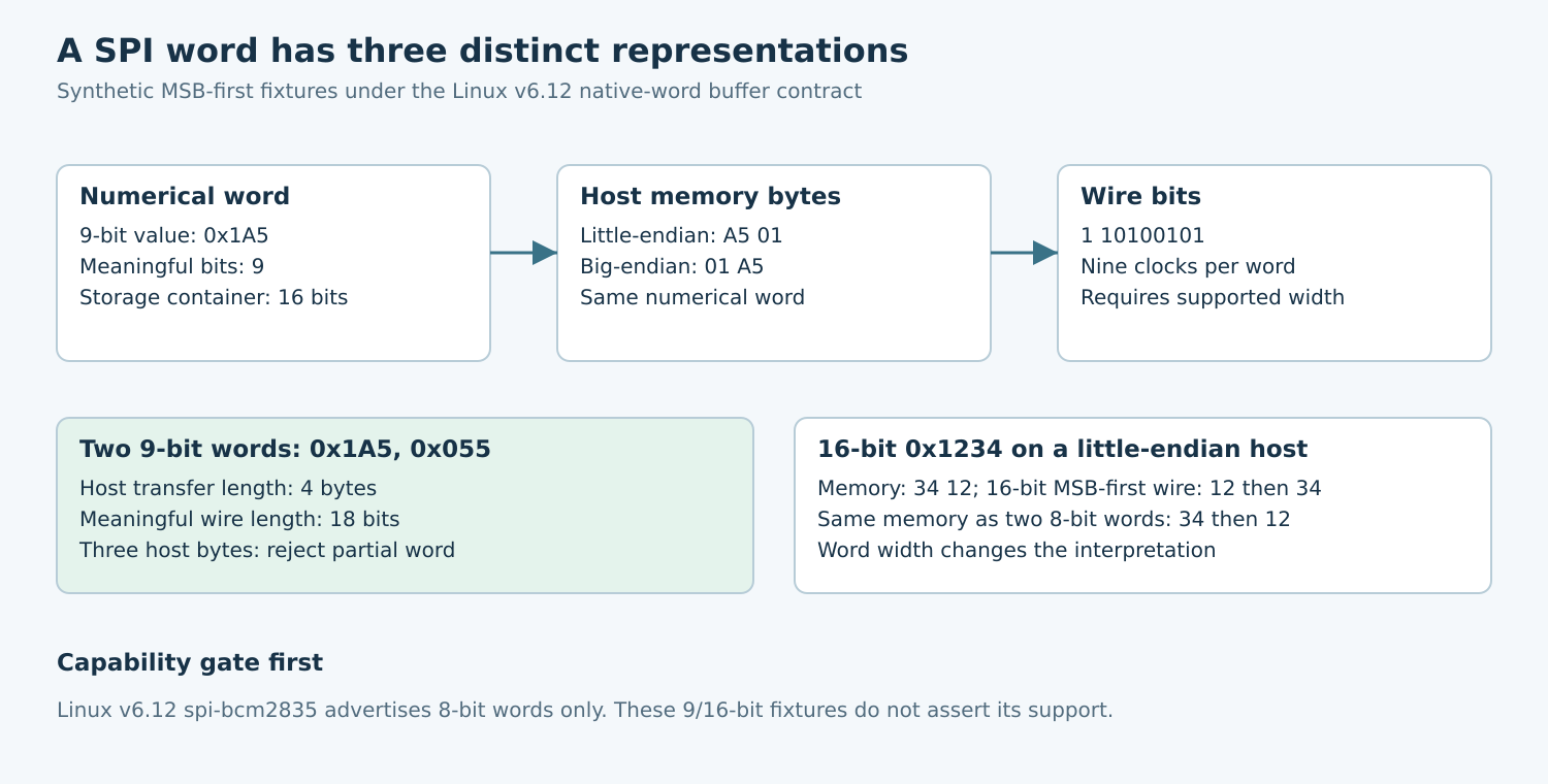
For example, the Linux v6.12 spi-bcm2835 driver advertises SPI_BPW_MASK(8). Treat that implementation as supporting eight-bit words through this interface. Do not infer capabilities from a board family name or from a different auxiliary-controller driver. A later driver version must be checked independently.
The capability gate belongs before buffer construction. If the required width is unsupported, stop with a clear configuration error. Silently changing nine to eight bits changes the protocol. An alternative packing scheme is acceptable only when the peripheral explicitly permits the resulting bit stream and framing, and the chosen host path can reproduce it.
2. Write the representation contract
The v6.12 SPI transfer documentation specifies native CPU byte order for in-memory words. Non-byte-sized words are right-justified in their storage containers. Unused transmit bits and undefined receive bits occupy the upper positions. Bit order on the wire is a separate setting.
For a hypothetical MSB-first nine-bit word with value 0x1A5, the meaningful wire sequence is 1 10100101. In a sixteen-bit host container, a little-endian CPU stores bytes A5 01; a big-endian CPU stores 01 A5. Both represent the same word. With a correctly supported nine-bit transfer, the unused seven upper container bits are not seven additional wire clocks.
For a hypothetical sixteen-bit value 0x1234, little-endian memory contains 34 12. An MSB-first sixteen-bit transfer sends the word’s upper eight bits before its lower eight bits. In contrast, two eight-bit words constructed from the same raw memory bytes send 34 and then 12. Changing bits per word without changing the buffer contract can therefore reverse the apparent byte order.
3. Calculate length in host bytes
The spidev transfer ABI defines len in bytes and provides a separate bits_per_word field. Neither field is a count of logical application records. Keep names such as word_count, storage_bytes_per_word, and transfer_bytes distinct in the wrapper.
The v6.12 SPI core validation uses a one-byte storage unit for widths up to eight, two bytes for widths up to sixteen, and four bytes above that within the core’s supported width range. It rejects a transfer length that is not a multiple of that storage unit, as well as unsupported word widths.
Two nine-bit words therefore require four host-buffer bytes under this contract, although the meaningful transfer contains eighteen serial bits on a conventional single-data-line link. A length of three bytes is a partial storage-word error, not a request for twenty-four clocks or one-and-a-half nine-bit frames. Validate the arithmetic before issuing the operation.
4. Construct fixtures that expose accidental byte swapping
Use asymmetric patterns. Values such as all zeros, all ones, or repeated bytes conceal many ordering faults. A useful synthetic set includes 0x1A5 and 0x055 for nine-bit framing, and 0x1234 and 0xA607 for sixteen-bit framing. List each word’s numerical value, expected native-memory bytes on the test host, and expected wire bits.
Build host words with appropriately sized integer storage rather than casting an arbitrarily aligned byte pointer. At a serialization boundary, perform explicit loads and stores that preserve the native-word contract. Do not apply a blanket network-byte-order conversion just because the peripheral sends its most significant bit first.
For received nine-bit words, mask to the meaningful nine-bit range before comparing payload values. Undefined upper receive bits are not status flags. If a target protocol assigns a command/data meaning to one of the nine meaningful bits, decode that bit separately; the SPI transport does not know its application meaning.
5. Test rejection paths as well as happy paths
- Supported-width test: establish which widths the deployed driver accepts. Record the returned error for a deliberately unsupported request on a safe test setup.
- Partial-word test: require the wrapper to reject three bytes for a nine-bit or sixteen-bit transfer before hardware access.
- Representation test: compare synthetic word arrays with expected host bytes for the host’s endianness. Keep wire-bit expectations in a separate fixture.
- Receive-mask test: vary undefined upper container bits while holding meaningful bits constant. The decoded payload must remain unchanged.
- Configuration test: confirm that per-transfer overrides and device defaults cannot silently disagree about width or bit order.
When hardware is available, capture a short known pattern at the target pins. Count clocks per logical word and compare the sampled bits with the fixture. An analyzer configured to decode eight-bit bytes can display misleading groupings for a nine-bit exchange; inspect its word-width setting or the raw edges.
6. Keep the acceptance artifact portable
Save the kernel release, bound driver, accepted width, bit order, host endianness, storage size, transfer length, raw receive words, and annotated capture together. The artifact should let another engineer explain every host byte without guessing whether it represents payload, padding, or a second word.
No SPI transaction or hardware capability test was performed for this article. The examples specify expected representation behavior from the pinned interface. Passing a software fixture verifies packing logic only; target qualification still requires accepted configuration and a matching physical waveform.