STM32G474 ADC Oversampling: Prevent a Large Accumulation from Wrapping the 16-Bit Result
Increasing the STM32G474 ADC oversampling ratio can make a result wrap instead of simply becoming smoother. The accumulator can hold more bits than the final data register. Choose the right shift from the maximum admitted sum and tell the consumer what scale the resulting code represents.
The scope is one single-ended, 12-bit regular-conversion stream with unsigned raw codes and no additional gain or offset compensation. RM0440 Rev 9, section 21.4.29 and Table 175 define the oversampling datapath. The numerical cases below are arithmetic checks; no ADC samples, noise measurements or effective-resolution results were collected.
Treat accumulation and output width separately
For a ratio of 256 and an individual full-scale code of 4095, the accumulated sum is:
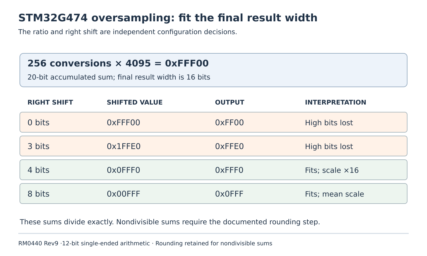
256 * 4095 = 1048320 = 0xFFF00That needs 20 bits. The manual describes a right shift, truncation to the 16-bit result width and rounding using bits discarded by the shift. If the shifted intermediate exceeds 16 bits, it is truncated without saturation. A large input can therefore lose high bits rather than becoming a stable maximum reading.
ADC_CFGR2.OVSR selects the ratio and OVSS selects the shift. They are independent fields. Use the register definition in section 21.7.5: OVSR = 111 selects 256, while OVSS = 0100 selects four shift bits. A ratio setting by itself does not request an average divided by that ratio.
Keep these decoded settings with the acquisition configuration. A log containing only “oversampling enabled” is insufficient to interpret its values after a firmware change.
Compare three interpretations of the same sum
With the full-scale sum above, no shift leaves 0xFFF00; retaining its low 16 bits produces 0xFF00, or 65280. A three-bit shift leaves 0x1FFE0, still too wide, and the final result is 0xFFE0, or 65504. Neither value represents saturation at the output maximum.
A four-bit shift gives 0xFFF0, or 65520, which fits. An eight-bit shift gives 0x0FFF, or 4095. These divisions are exact for this particular full-scale sum, so rounding does not change them.
The four-bit result has sixteen times the average raw-code scale for the stated 256-conversion configuration. The eight-bit result uses the original raw-code scale for the rounded mean. A consumer that divides both by the same hard-coded full-scale number introduces a scaling error even when neither result wraps.
Document the conversion back to the intended quantity with the actual ADC transfer model, reference and calibration. More output digits do not establish more analog accuracy. A 16-bit container cannot certify 16 effective measurement bits.
Use a monotonicity counterexample to expose wrapping
A full-scale test alone can be misleading because a wrapped value may still look large. Consider a separate fixed ratio of 32 with no shift and constant individual codes:
32 * 2047 = 65504 = 0xFFE0
32 * 2048 = 65536 = 0x10000
After the documented 16-bit truncation, those sums become 65504 and 0. A one-count increase in every raw conversion creates a dramatic decrease in the stored output. This original arithmetic fixture isolates width loss without any analog noise or timing assumption.
An increasing-input test should therefore inspect the whole intended range, particularly the first width boundary. Software clamping after reading the already-wrapped value cannot infer the discarded high bits. Prevent the overflow through a suitable ratio/shift contract instead.
Preserve rounding in the numerical model
Do not model every result as a floor-only right shift. Figure 131 gives accumulated value 0x3B7D7 with a five-bit shift and final rounded result 0x1DBF. A floor-only calculation would instead give 0x1DBE.
Keep this documented nondivisible case alongside the exact full-scale cases in a decoder test. It checks a different property: whether the model includes rounding at all. This example does not establish a universal tie-breaking rule for every half-way case; qualify any such requirement against the precise hardware behavior.
When deriving a maximum, include the allowed raw-code range and any configuration changes that alter it. A calculation based only on nominal sensor values leaves no protection against a permitted higher input. Differential conversion and extra gain/offset paths require their own analysis and are outside this fixture.
Deliver a scale contract with the firmware
The proposed acceptance record contains resolution, single-ended mode, ratio, shift, maximum permitted sum, rounded output interpretation and downstream unit conversion. Reconfigure the relevant fields only under their documented idle-state requirements; do not treat an arithmetic recommendation as permission to rewrite active acquisition settings.
A later controlled hardware check should compare stable legal input levels across the chosen operating range and retain raw data before application conversion. Separately qualify any claimed noise benefit or extra effective resolution. The completed numerical review answers a narrower question: the accepted input range fits the final result width, and every consumer understands that result’s scale.