Gateway Buck Inductors: Separate Saturation Current from Current-Limit Protection
A gateway’s 3 A power rail does not imply that its buck inductor carries at most 3 A. Normal switching ripple already raises the peak above the load current. Startup and fault protection introduce another envelope, and a current limit cannot be assumed to stop the current before an unsuitable inductor loses most of its inductance.
The concrete reference is Texas Instruments LMR33630 datasheet SNVSAN3F, revised November 2020. Its inductor-selection section distinguishes saturation behavior from nominal inductance, while its protection description separates peak and valley current limits. The numerical example below is an independent ideal buck calculation, not a validated LMR33630 component selection.
Calculate the switching ripple first
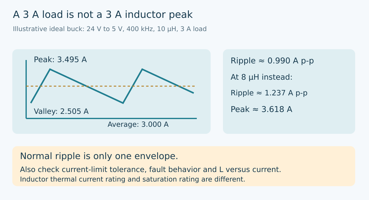
Assume a hypothetical continuous-conduction buck converts 24 V to 5 V at 400 kHz, with 10 µH effective inductance and a 3 A load. Neglect switch and wiring losses. Ideal duty ratio is VOUT/VIN = 5/24, approximately 0.2083, so high-side on-time is about 0.5208 µs.
During that interval, the inductor sees approximately 19 V. Its current change is voltage times time divided by inductance: 19 V × 0.5208 µs / 10 µH, approximately 0.9896 A peak-to-peak. In steady continuous conduction, the triangular ripple is centered on the 3 A load current.
The resulting peak is approximately 3.4948 A and the valley approximately 2.5052 A. Choosing a component solely because its catalog entry contains “3 A” would leave the meaning of that rating unresolved before any overload occurs.
Now suppose effective inductance is 8 µH rather than 10 µH. With the other assumptions unchanged, ripple rises to approximately 1.2370 A peak-to-peak and the peak becomes 3.6185 A. This comparison can represent a tolerance study, but it must not be silently treated as a complete saturation model. Actual inductance changes with current and temperature require the selected component’s curves.
Keep thermal and saturation ratings separate
An inductor’s thermal-current rating usually relates to an allowed temperature rise under stated mounting and environmental conditions. Its saturation-current rating instead describes a specified reduction in inductance under magnetic bias. Those quantities answer different questions and may use different test conditions.
Record the manufacturer’s definition beside each value. A saturation rating based on a 30% inductance reduction is not directly equivalent to one based on a 10% reduction. Even before a nominal threshold is reached, changing inductance changes the switching slope and peak-current estimate.
For the ideal triangular waveform above, RMS current is √(IOUT² + ΔI²/12), approximately 3.0136 A. If an illustrative winding resistance were 30 mΩ at the relevant temperature, copper loss from that RMS current would be about 0.2724 W. This calculation covers only resistive winding loss under the assumed waveform; it excludes core loss and temperature-dependent changes.
That modest RMS increase does not make the peak irrelevant. Heating and magnetic saturation are separate constraints. A part can satisfy a thermal-current number while its inductance has already fallen too far for the converter’s intended behavior.
Build a second envelope for protection
LMR33630 documentation recommends checking saturation against the high-side switch current limit and warns that a saturated inductor can develop current very rapidly. The electrical-characteristics table gives a high-side current-limit range rather than one exact value and notes that the entries are tested open-loop; closed-loop application behavior can differ.
For design review, do not compare the inductor only with a typical limit. Use the applicable upper-bound information and the manufacturer’s application guidance, including the actual operating conditions and any uncertainty in the dynamic response. If a design needs a guarantee that the available documentation does not provide, resolve that gap before qualification.
Peak limiting and valley limiting are not synonyms. A peak limit responds to the upper part of the switching waveform. A valley constraint affects whether another energy-delivery interval may begin. The selected device may combine these with frequency changes or hiccup operation. A system-level “overcurrent protected” label does not identify which instantaneous current the magnetic component can experience.
Keep normal-operation ripple, transient response and fault behavior as distinct rows in the review. Passing the 3.4948 A nominal peak calculation only closes the first row.
Understand why inductance collapse changes the risk
For a fixed applied voltage, current slope is V/L. Under the example’s 19 V on-state voltage, 10 µH gives 1.9 A/µs. A hypothetical fall to 2 µH would raise that instantaneous slope to 9.5 A/µs. The current would change five times faster while that voltage remained applied.
This is a local slope comparison, not a prediction that a specific inductor collapses to 2 µH or that a controller waits a specified time. It explains why finite sensing and switching response matter. Protection designed around a normal inductance cannot be assumed to provide the same current envelope after the magnetic component changes dramatically.
Do not deliberately drive an unqualified board into hard saturation to discover its limit. Begin with manufacturer curves and a bounded model. Any later overload test needs controlled low-voltage equipment, current limiting, suitable probes and an agreed stress envelope.
Release a component-specific current budget
The review package should state input and output ranges, switching mode, frequency, load range, minimum effective inductance, winding resistance and the exact saturation definition. Preserve the relevant current-limit bounds and fault behavior with the controller revision. Generic family names are insufficient when variants differ in frequency or current capability.
For hardware verification, observe inductor current and the switch-node timing together where practical. A changing current slope can be informative, but probe bandwidth, insertion effects and operating-mode transitions must be considered before assigning a cause. Record temperature and supply conditions rather than retaining only a successful room-temperature waveform.
The resulting decision is more specific than “use an inductor above the output current.” Select the magnetic component for the ripple it normally carries, the temperature it reaches and the current envelope the converter can actually impose. Those are related checks, not interchangeable ratings.
Primary reference and trend scope
The preserved Google Trends RISING row “industrial iot solutions,+110%,” worldwide, all categories, web search, July 19–October 19, 2026 supports the parent integration topic only. It does not establish search growth for inductor saturation or this article title.