ADC Reference Drift: Separate Input Changes from a Moving Measurement Scale
A changing ADC code can reflect a changing input, a changing reference, or both. Observe the signal and reference independently, then compare their ratio with the raw code. For a ratiometric sensor, deliberately sharing the excitation/reference relationship can cancel a common change, but only when the complete signal paths preserve that relationship.
Applicability: Microchip MCP3008 datasheet DS20001295E, 2022, supplies the concrete ten-bit transfer model. The worked voltages are hypothetical arithmetic examples, not measured drift or guaranteed accuracy. Reference-device selection, board layout, and calibration require the actual component specifications and operating conditions.
1. Write the conversion model before diagnosing drift
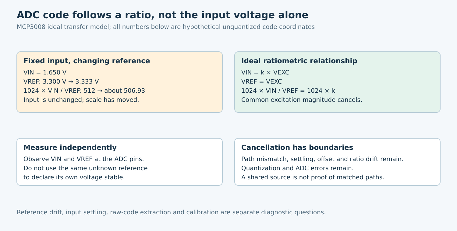
The MCP3008 reference-input section relates the ideal code to 1024 times VIN divided by VREF and defines the LSB scale from VREF. Real output also includes quantization, offset, gain, nonlinearity, noise, and input-settling effects.
Keep the ideal ratio separate from the integer output. Do not treat the ideal expression as a promise of an exact code at a transition boundary. For small changes away from saturation, its relative sensitivity is approximately the relative input change minus the relative reference change.
In a hypothetical case, VIN stays at 1.650 V while VREF changes from 3.300 V to 3.333 V. The unquantized ideal code coordinate moves from 512 to about 506.93. The input did not fall; the measurement scale increased. The one-percent reference change is chosen for illustration and is not an MCP3008 or reference-device drift specification.
2. Observe the reference at the point of use
Measure the voltage at the ADC reference pin relative to the relevant analog ground, not only at the reference source’s output connector. Include supply voltage, temperature, load state, and sampling configuration in the record. Wiring drop or ground movement can make two nominally identical reference observations differ.
Use an independent, suitable instrument or an independently referenced measurement path. Measuring the reference through an ADC whose scale is that same reference can hide the change: the ratio may remain nearly constant. Document the instrument’s own accuracy, loading, bandwidth, and calibration status.
Separate slow drift from dynamic disturbance. Analog Devices’ SAR reference-design discussion explains why reference drive and transient loading matter. A stable average voltage does not establish that the reference remains settled during each conversion. Select observation bandwidth and probing to match the suspected mechanism.
3. Use a signal/reference experiment matrix
- Stable input, normal reference: establish raw-code variation while recording both physical voltages.
- Stable input, independently controlled reference: vary the reference only within the selected ADC’s permitted range and predict the ratio change before testing.
- Controlled input, stable reference: vary the input with the reference held independently stable, separating input-path gain from reference behavior.
- Shared excitation case: vary the common excitation within all sensor, ADC, and reference limits while checking whether the intended ratio remains constant.
Keep sample timing, acquisition conditions, channel order, filtering, and software scaling fixed during each comparison. Otherwise an apparent reference correction can actually be a settling or averaging change. Use raw codes first and preserve the original scale metadata.
If raw code follows the measured VIN/VREF ratio, investigate the two analog sources before changing the decoder. If the ratio remains stable while codes move, inspect other error terms, including reference transients not resolved by the measurement, ADC behavior, input settling, and data integrity.
4. Understand what ratiometric cancellation removes
For an ideal resistive sensor arrangement, let VIN = k times VEXC and VREF = VEXC. Substitution gives an ideal code coordinate of 1024 times k: the common excitation magnitude cancels. Analog Devices’ ADC error discussion describes this ratiometric principle.
The cancellation depends on the actual circuit. Separate filters, amplifiers, lead resistance, ground drops, and unequal settling can make the signal and reference respond differently. A common source does not guarantee identical instantaneous values at the ADC pins.
It also does not remove sensor nonlinearity, resistor-ratio drift, amplifier offset, ADC nonlinearity, or quantization. If the product needs an absolute voltage rather than a ratio, cancelling excitation variation may not answer the measurement question at all. Define the physical quantity before choosing the reference architecture.
5. Build an explicit error budget
List reference initial tolerance, temperature behavior, long-term behavior, noise, load regulation, and startup settling from the chosen reference’s datasheet. Add ADC error terms at the actual supply, reference, sampling, and temperature conditions. Keep typical characteristics separate from guaranteed limits.
For each term, state whether it is calibrated out, bounded by a component specification, measured on the board, or still unknown. Do not combine unrelated typical values into a claimed worst-case accuracy. If using statistical combination, document independence and distribution assumptions rather than applying root-sum-square automatically.
Calibration needs a defined input standard and operating scope. A room-temperature gain correction cannot establish behavior across temperature, time, and load without evidence. Preserve calibration version and reference conditions with the measurement configuration so firmware changes cannot silently reinterpret old coefficients.
6. Qualify the final interpretation
Repeat the matrix across the intended operating conditions, using approved sources and safe input limits. Compare absolute measurements and ratio-derived predictions, including their uncertainty. Where the design is ratiometric, test disturbances that affect the two paths differently as well as disturbances common to both.
Report what changed in physical units, what changed in raw codes, and what model explains the difference. “The reference was nominally 3.3 V” is weaker evidence than a contemporaneous pin-level observation with known uncertainty. More averaging can reduce random variation while leaving reference-induced gain error untouched.
No ADC or reference measurement was performed for this article. The deliverable is a signal/reference experiment matrix and an error-budget worksheet. Acceptance requires a justified relationship between the raw code and the desired physical quantity, with reference drift and ratiometric assumptions stated explicitly.