ifm AL1432 Power Planning: Check Port, Module and Daisy-Chain Limits Separately
The AL1432’s configurable 2 A port rating does not provide 2 A
simultaneously to every sensor port. The product has separate aggregate
supply limits, and forwarding power to another module introduces another
current path. An EtherCAT layout can be logically correct while its
power plan exceeds one of these boundaries.
Use the AL1432-00 EN-GB datasheet dated January 24, 2025, together
with operating manual 11489157/02, February 2024. This is a
design-review method for qualified personnel, not an installation
drawing or approval to connect live equipment.
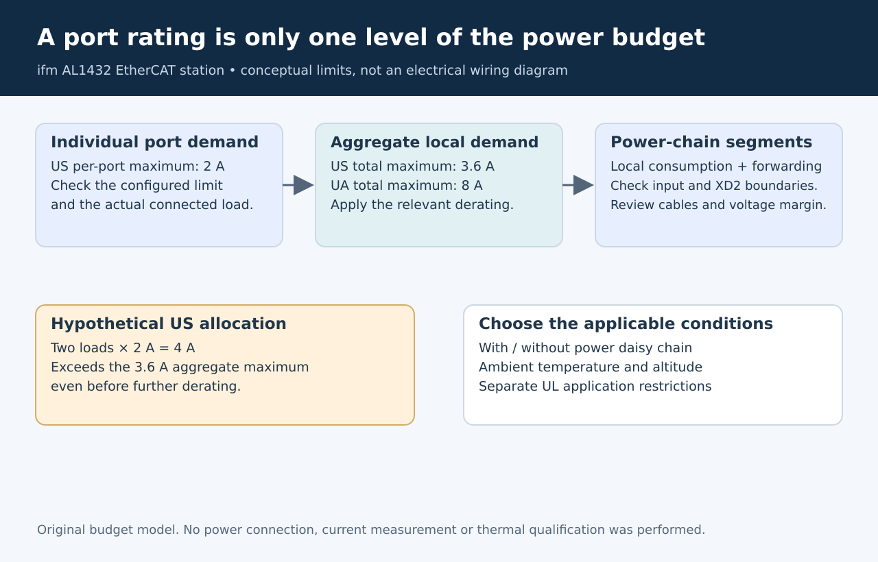
Original budget hierarchy. Values shown are documented limits or
hypothetical arithmetic, not measurements.
Do not multiply the
per-port maximum
The datasheet gives a 2 A adjustable per-port rating for sensor
supply US, but a 3.6 A total US load limit. Actuator supply UA has its
own 8 A total limit and 2 A per-port rating. These are different
constraints, not alternative ways of describing one interchangeable
power pool. AL1432
datasheet, electrical data
For a deliberately simple hypothetical case, two US-powered loads
each demanding 2 A would total 4 A. Each individual demand matches the
listed per-port maximum, yet their sum exceeds the listed 3.6 A
aggregate maximum before considering any further derating. Raising a
port’s configured limit cannot repair that arithmetic.
Build separate US and UA ledgers from the actual connected devices.
For each load, identify its supply path and the manufacturer’s relevant
operating and transient requirements. Do not substitute a typical
reading for the maximum demand used in the design decision.
Account for power
passing through the module
The AL1432 manual identifies XD1 as Power IN and XD2 as Power OUT. US
and UA are looped through to supply an additional device. Consequently,
an upstream cable and connection can carry downstream demand as well as
the local module’s demand. AL1432
manual, sections 6.7 and 6.8
Draw the power chain beside the EtherCAT topology. They need not have
identical branch points. A network cable identifying the next EtherCAT
device does not establish which module supplies that device’s power.
For every chain segment, list what is consumed locally and what
continues downstream. Check the applicable input, local-load and
forwarded-current limits, as well as the selected cables, connectors and
protection. Include the module’s own consumption in the feed calculation
rather than accounting only for its attached sensors.
If the budget fails, a separately engineered feed or different
grouping may be necessary. Do not solve the discrepancy by assuming that
unused capacity on UA can be transferred to US or that another module
removes the upstream load.
Select the correct derating
case
Manual section 6.7.1 presents different curves for operation with and
without a daisy chain. It also differentiates altitude and gives a
separate UL-application case. The listed derating measurements use 24 V
supplies. A single headline current figure therefore cannot describe
every permitted installation condition.
Use the curve and restrictions applicable to the actual arrangement.
Record the local ambient-temperature assumption, altitude, certification
context and whether power is forwarded. Do not interpolate a new
guaranteed limit from a small reproduced image or use the no-chain case
for a chain installation.
Voltage margin is a separate check. A current budget below the limit
does not prove the farthest module receives adequate supply voltage
through the selected cable under load. Evaluate that path with the
actual cable and supply characteristics.
Release a
budget that matches the assembled station
The review should produce one traceable load allocation per port and
one current/voltage assessment per power segment. When a sensor,
actuator or downstream module changes, revisit the affected upstream
segments rather than checking only the replaced device’s connector.
Later qualification must use the approved installation and operating
conditions, with electrical work performed by qualified personnel. No
load, temperature-rise or voltage-drop measurements were performed here.
Passing the arithmetic review is a prerequisite for that work, not
evidence that the assembled station has already passed it.