LVDT Gateway Inputs: Preserve Direction Through the Demodulation Reference
A series-opposed LVDT can produce the same secondary-voltage magnitude at two positions on opposite sides of its mechanical null. A gateway that retains only an unsigned RMS value can therefore lose the very information needed to distinguish those positions. Direction is carried by the relationship between the secondary waveform and the excitation reference, not by amplitude alone.
This makes the demodulation reference an explicit part of the sensor interface. The review must identify which waveform supplies timing, how its phase relates to the measured secondary, and what happens as the useful secondary signal approaches zero. A higher-resolution ADC cannot recover direction that was discarded earlier in the signal path.
Specify the winding topology first
Analog Devices’ AD698 datasheet distinguishes series-opposed and half-bridge LVDT connections. Its series-opposed description associates output amplitude with displacement and phase with direction. Its half-bridge arrangement uses a different voltage relationship and does not present the same null behavior.
The wiring contract should therefore identify the actual sensor topology, winding connections, polarity, excitation conditions, and the physical definition of positive displacement. Avoid treating every device marketed as an LVDT as interchangeable at the connector. The names “A” and “B” are especially easy to misread: they can denote winding signals in one architecture and demodulation channels in another.
Before reviewing firmware units, annotate the schematic with the secondary signal being measured and the reference used to interpret its sign. Preserve that mapping in the acquisition configuration. This provides a concrete answer when an installation reports correct magnitude but reversed motion.
Why an unsigned measurement loses information
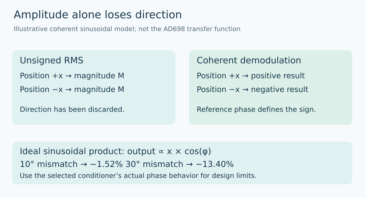
Consider a simplified sinusoidal model in which the secondary voltage is K times position x times sin(ωt), where K is positive and the phase reference is the excitation. Positive and negative positions change the sign of the waveform. Its RMS magnitude is proportional to the absolute value of x, so an RMS-only conversion maps both positions to the same number.
A coherent demodulator retains the relationship to the reference. For an illustrative sinusoidal multiplier, multiplying by sin(ωt) and averaging over complete cycles produces Kx/2. The result preserves the sign of x. That expression is a teaching model, not a claim that the AD698’s internal demodulators implement this exact multiplier or scaling.
This distinction should shape a bench demonstration. Two known positions equally spaced around null should produce opposite signed displacement readings, not merely equal amplitudes. An unsigned diagnostic waveform can still be useful, but it should not silently replace the signed position channel.
Phase error can look like a scale change
Extend the ideal model by adding a phase error φ to the secondary waveform relative to the demodulation reference. The averaged sinusoidal product becomes Kx cos(φ)/2. In this model, a 10-degree mismatch reduces the recovered magnitude by approximately 1.52%; a 30-degree mismatch reduces it by approximately 13.40%.
Those calculated values explain a possible mechanism, not a permissible phase-error specification. The selected conditioner has its own demodulation behavior and limits. The AD698 documentation specifically notes that primary-to-secondary phase shift can require a compensation network. Follow that device’s design procedure rather than using the cosine example as its guaranteed error curve.
A scalar gain calibration at one excitation frequency and cable arrangement may absorb a particular phase-related error without proving that the relationship remains stable elsewhere. If the supported installation changes the cable, excitation frequency, or sensor model, revisit the reference relationship. Do not assume a constant phase correction merely because one static position calibrated correctly.
Do not derive a fragile reference from the null
The secondary signal becomes small near the series-opposed null. A timing detector that relies on that shrinking signal can become more sensitive to noise just where the application expects a clean zero crossing in displacement.
The AD698 datasheet describes using the primary channel to trigger the secondary-channel demodulator because the secondary channel may reach zero at null. This is a circuit-specific design feature worth preserving in an integration review. It is not a general instruction to connect an arbitrary primary voltage directly to a digital input.
For a custom digital demodulator, document how reference timing remains available when displacement is near zero. Define the reference-input range, acquisition synchronization, and behavior when a valid reference is unavailable. The reference needs its own validity condition; a last known phase value should not automatically authorize fresh position data indefinitely.
Excitation normalization solves a different problem
A ratio between secondary signal and observed excitation can reduce sensitivity to excitation-amplitude changes in an appropriate architecture. It does not inherently restore lost phase information or make a missing reference usable. The denominator must be valid and within the chosen circuit’s operating range.
Keep three questions separate: is the excitation present and suitable, is the secondary waveform interpreted with the correct phase relationship, and is the resulting displacement scaled correctly? A single “sensor value valid” bit can conceal which condition failed. Diagnostic status can distinguish them without claiming that a zero displacement alone proves a healthy or a failed sensor.
The AD698’s channel ratio also differs from conditioners that use the difference and sum of two secondary amplitudes. Do not copy an equation between those architectures based only on similar signal names. The exact reference definition belongs beside the transfer equation.
Preserve direction in the acceptance record
Use independently known mechanical positions within the sensor’s specified travel. Include positions on both sides of null and record the sign convention before taking data. Capture the excitation reference and secondary waveform together where suitable instrumentation permits, along with the final signed result and configuration.
If a result reverses sign, inspect wiring polarity and reference phase before applying a software sign flip. A sign change can be intentional configuration, but it should be tied to the physical coordinate system rather than used to conceal an unexplained connection difference.
No sensor measurements or closed-loop qualification are reported here. The deliverable is a phase-reference argument: the winding topology, reference source, sign convention, and valid-data conditions agree. Only then does converting the recovered signal into millimeters become a well-defined operation.
Primary reference and trend scope
Analog Devices AD698 datasheet, Revision D, Theory of Operation and Connecting the AD698 supplies the device-specific foundation. Sinusoidal multiplication examples are explicitly simplified analytical models.
Topic selection follows the preserved Google Trends RISING row “industrial iot solutions,+110%,” worldwide, all categories, web search, July 19–October 19, 2026. That parent-topic evidence does not establish rising searches for LVDTs or this title.