BiSS C Encoder Links: Separate Cable-Delay Compensation from Sensor Processing Time
A BiSS C encoder works with a short bench cable, but the master loses frame alignment after the final machine cable is installed. Another encoder uses the same cable yet holds the start bit back for longer. These are not necessarily the same timing problem. The first can involve transport delay between clock generation and returned data; the second can involve the sensor preparing the captured measurement.
This article is scoped to the point-to-point behavior in BiSS C Protocol Description Revision D2, especially “Line Delay,” “Processing Time,” and the characteristics table. It does not describe BiSS Line, invent a device-specific maximum clock rate, or report hardware testing. Any implementation must also follow the actual master and encoder documentation.
Identify which edge the delay follows
The master-side MA signal and the slave-side MAI signal are not simultaneous when the connection has propagation delay. The returning SLO-to-SL path adds another delay. A capture taken only at the master therefore contains the combined effect of outward transmission, slave response, and return transmission. Moving the oscilloscope to the encoder changes the reference point, not the physical cable.
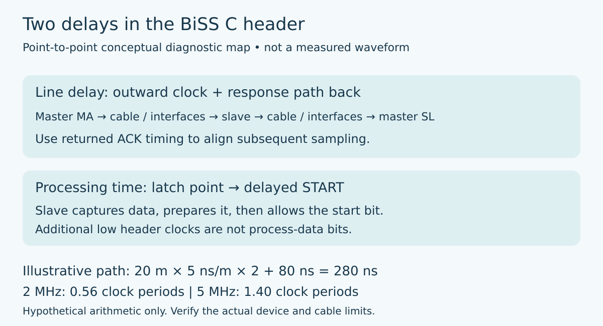
Revision D2 describes line-delay compensation through the returned acknowledge transition. The master can extend the header with additional clocks until it receives the acknowledge, then use the timing within the final acknowledge-clock period to adapt subsequent sampling. That is more capable than assuming that every returned bit can always be sampled at one fixed phase of the locally generated clock.
For a master implementation review, ask where that adaptation happens. It may be implemented in a dedicated peripheral, FPGA logic, or another documented interface block. A software API that accepts a clock frequency does not itself establish that the receive sampling point compensates for the installed path. Verify the actual capability rather than inferring it from a successful short-cable transaction.
Use a round-trip model, not the cable length alone
Take a deliberately simplified example: a 20 m cable, propagation of 5 ns per meter in each direction, and 80 ns of combined additional interface delay. The outward cable contributes 100 ns and the return cable contributes another 100 ns, giving an assumed total of 280 ns. At a 2 MHz clock, one period is 500 ns, so that delay is 0.56 of a clock period.
At 5 MHz, the period is 200 ns and the same assumed path represents 1.40 periods. This does not establish that either frequency is legal for a particular encoder, master, or cable. It demonstrates why rounding the timing budget to “less than a microsecond” is inadequate. The delay must be compared with the bit period and the supported compensation behavior.
The 80 ns term is a placeholder, not a universal transceiver specification. Replace it with the relevant device and implementation limits, including any isolators or translators in the path. Also distinguish total delay from uncertainty and jitter. A consistent delay that is correctly compensated is a different constraint from an edge whose arrival moves close to the sampling boundary.
Processing time begins with measurement capture
A point-to-point slave can require time to prepare its process data after the latch point. Revision D2 describes the processing interval from the latch point to the start bit. When more time is needed, the slave continues the low state after acknowledge rather than immediately producing the start bit. The later start therefore has a defined role in the header.
A parser that jumps directly from a detected acknowledge to a fixed payload position can misinterpret this legitimate extension. It must recognize the frame structure supported by the interface, with bounded handling of the permitted processing interval. Treating the additional clocks as payload shifts the interpretation before the measurement bits even begin.
Do not fold that interval into a cable-length estimate. A sensor’s processing behavior and the transport path have different causes and can change independently. A device substitution can alter start-bit timing without changing a centimeter of cable. A cable substitution can alter returned-edge timing without changing the sensor’s data-preparation algorithm.
Design the diagnostic capture around both intervals
A useful proposed capture first establishes the master’s local clock and returned-data signals. Identify the reference edge for the acknowledge timing measurement, then locate the acknowledge transition and eventual start bit. Preserve the original waveform alongside the decoder output. An incorrectly configured decoder can display plausible fields while hiding the header assumption that caused the error.
If accessible and safe in the approved setup, a corresponding slave-side capture helps separate transport effects from local data preparation. Account for probe skew and the measurement reference before subtracting timestamps from different channels or instruments. The precision claimed for a delay estimate cannot exceed the measurement setup’s ability to establish those relative times.
Compare a documented short cable with the intended installation cable while keeping the encoder and configuration fixed. Separately compare the supported operating modes of the same encoder without changing the cable. These controlled changes provide different evidence: the first primarily challenges the physical path, while the second can expose differences in measurement preparation. Neither experiment should exceed the actual product limits simply to force a failure.
Budget the entire cycle after the header works
Correct bit sampling does not guarantee the desired measurement update period. The cycle also has to accommodate header extension, process-data length, frame termination, and the required idle behavior. Use the worst permitted combination for the configured devices rather than calculating the schedule from payload bits divided by clock frequency alone.
If the resulting cycle does not fit, reducing data length or changing clock rate is an engineering change that needs the actual interface contract. Do not remove recognition of a delayed start bit merely to meet a host scheduling target. Likewise, line-delay compensation does not remove the cable’s electrical limits or authorize an unsupported clock frequency.
The integration record should retain the chosen clock rate, device timing requirements, compensation capability, installation path, and evidence for the identified acknowledge and start events. This makes the distinction durable: cable delay governs where returned bits arrive, while processing time governs when the slave is ready to begin its data. A reliable master handles both without confusing one for the other.
Primary reference
BiSS Association, BiSS C Protocol Description Revision D2, printed pages 5, 8–10 and 29.