ISO7741 Gateway Controls: Default Low Is Not the Same as Unpowered
An isolated gateway can have perfectly sensible firmware and still assert a control at the wrong moment. The risky assumption is that an isolator ordered with a default-low suffix always holds its output low. That description omits the output supply and output-enable state. A low-voltage control path needs a state contract for both sides of the barrier, not merely a preferred value in the processor’s startup code.
This example examines an ISO7741F channel used to carry an active-high transmit-enable request. It is a hypothetical design review, not a tested gateway or a safety-function implementation. The procedure applies to low-voltage logic domains; it does not describe insulation qualification or high-voltage testing.
Read the function table before assigning a safe state
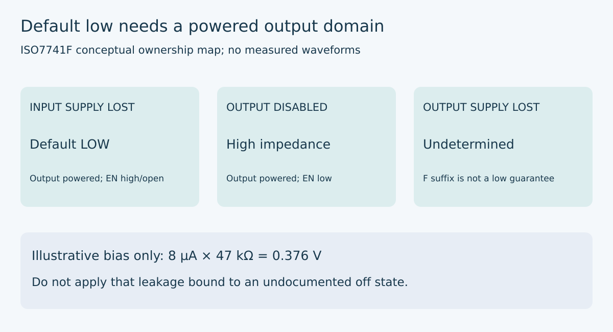
Texas Instruments’ ISO774x datasheet, SLLSEP4K, revised August 2026, Table 7-2 on page 29, distinguishes three cases. With the output side powered and enabled, a missing input-side supply selects the ordered default. Pulling output enable low instead makes the outputs high impedance. If the output supply is absent, the output is undetermined, not guaranteed low.
Consequently, the F suffix solves one defined communication-loss case. It does not turn an unpowered output into a guaranteed pulldown. Nor does disabling the channel preserve its previous low level. The circuit connected to that output must establish the required state whenever the output no longer actively controls it.
The same table flags an undetermined region between 1.7 V and 2.25 V and warns that a driven input can weakly power a floating input supply through protection circuitry. These are reasons to inspect actual rail trajectories rather than classifying every subnominal voltage as simply “off.”
Allocate ownership in each supply state
Draw the processor-side supply, isolator output-side supply, and transceiver logic supply separately, even if two share a nominal voltage. Identify where an enable pulldown returns and whether the receiving transceiver can remain powered after the isolator output side collapses.
For the ordinary powered state, the isolator owns the request and firmware owns the intended command. For input-side loss with a valid output supply, the selected default owns the command. For output-enable low, external bias or another explicitly designed gate must own it. For output-side loss, the receiving circuit needs an independently justified inactive-state mechanism; the isolator function table supplies no low-level guarantee.
Write those owners next to the schematic rather than hiding them in a boot checklist. If a state has two active drivers, review contention. If it has no guaranteed owner, record an unresolved electrical condition instead of treating the last observed level as retained state.
Calculate a bias requirement without inventing a device limit
Consider an illustrative high-impedance node with a 47 kΩ pulldown, a downstream maximum-low threshold of 0.8 V, and a separately established worst-case positive leakage budget of 8 µA. The static estimate is 8 µA × 47 kΩ = 0.376 V. Under those assumptions, the estimated low-level margin is 0.8 − 0.376 = 0.424 V.
These numbers are invented worksheet inputs, not ISO7741F specifications or a resistor recommendation. Every connected output, receiver, protection component, and fixture path must contribute to the real leakage budget under the relevant power state. In particular, the calculation cannot establish behavior for the datasheet’s undetermined unpowered-output case without a defensible bound for that case.
Also check the opposite state. At a hypothetical 3.3 V high, the pulldown alone draws 3.3 V / 47 kΩ, approximately 70.2 µA. Verify that the driving device still meets the receiver’s high threshold with all loads and tolerances. Strengthening the pulldown improves one inequality while increasing the other state’s load.
Separate recovery delay from ordinary propagation
The 5 V switching table on page 19 contains more than the familiar input-to-output delay. For the F variant, enabling an output into a high state has a maximum listed delay of 8.5 µs under that table’s conditions. The corresponding high-impedance-to-low transition is specified on a nanosecond scale. A design that uses output enable as a fast permission gate must examine the relevant transition, not borrow the ordinary data propagation figure.
For illustration, a 1 Mbit/s serial symbol lasts 1 µs. An 8.5 µs enable-to-high allowance therefore spans 8.5 symbol periods. This division is only a timing-budget comparison; it is not a claim that the gateway loses exactly that many bits. The actual transceiver enable delay, output load, supply conditions, and software sequence still determine the first valid transmitted symbol.
A robust sequence establishes the isolator’s required powered and enabled state, allows the applicable worst-case settling interval, and only then treats the downstream request as available. Do not transfer the 5 V timing entry to a different supply table without checking it.
Observe the boundary that software cannot report
Plan captures of both isolator supplies, output enable, the channel output, and the downstream enable pin in a suitably reviewed low-voltage fixture. Exercise input-side loss, output-side loss, channel disable, and recovery as separate cases. The first successful firmware log occurs too late to establish what the control pin did during a supply transition.
Define acceptance at the receiving pin using that receiver’s actual thresholds and sequencing limits. Keep instrument loading in the circuit model, especially where external bias is weak. A probe or debug connection can provide a return path that will not exist in the deployed gateway.
The release artifact should be a completed supply-state matrix, a bias worksheet with sourced bounds, and captures for the supported transitions. Default-low is valuable when its preconditions hold. The engineering task is to ensure that every other permitted state also has an explicit, justified owner.
Source and demand context
Primary source: TI ISO774x datasheet, SLLSEP4K, August 2026, Table 7-2 and notes, page 29; 5 V switching characteristics, page 19. The local package preserves the PDF and page snapshots. Arithmetic and review examples are original and hypothetical.
The preserved Google Trends export shows “industrial iot solutions” rising 110% under “industrial iot,” Worldwide web search, all categories, July 19–October 19, 2026. This supports the broader gateway topic, not a measured increase in searches for this isolator or this article.