Rust Embedded Graphics Raw Images: Validate Row Packing Before Shipping an Asset
A raw image that draws without an error can still be the wrong height, show shifted rows, or swap its colors. In embedded-graphics 0.8.2, ImageRaw::new receives a byte slice and a width. It derives the height rather than checking an independently declared image size. Asset generation therefore needs its own validation boundary before those bytes enter firmware.
This article follows the pinned crate documentation and source. The examples are calculated fixtures and proposed checks, not results from compiling Rust or testing a display. They assume a working drawing target so that asset interpretation can be inspected independently of panel communication.
Specify the complete asset contract
Keep width, intended height, pixel color type, byte order and generated byte count together. Record the converter settings alongside the asset. A filename such as warning.raw does not convey enough information to reconstruct its layout.
The ImageRaw reference states that rows using fewer than eight bits per pixel begin on whole-byte boundaries. It also provides distinct big-endian and little-endian aliases for multibyte colors. These are interpretation choices made by the consuming type, not information discovered inside an opaque raw file.
Use a small, non-square calibration image before accepting the actual artwork. Mark its first and last columns differently and give each row a recognizable pattern. An all-black logo can conceal an incorrect row boundary; a symmetric icon can conceal an accidental reversal.
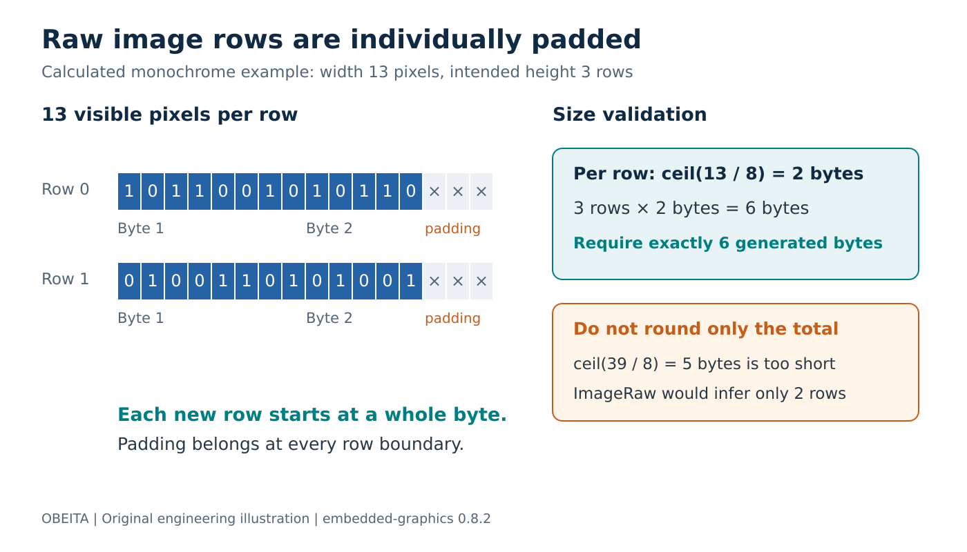
Original storage-layout diagram. The byte counts are arithmetic examples, not a device memory capture.
Round each row rather than the whole image
For a one-bit image 13 pixels wide and three rows high, each row needs two bytes. The complete asset therefore needs six bytes, even though its 39 visible bits fit mathematically into five bytes when packed continuously.
The distinction is where padding occurs. Each 13-bit row contains three trailing padding bits before the next row begins. Packing all rows into one continuous bitstream moves the second row three bit positions away from the location expected by ImageRaw.
For the supported raw formats, the constructor implementation calculates bytes per row as the rounded-up product of width and bits per pixel divided by eight. Its inferred height uses integer division of the byte-slice length by that row size. A final incomplete row is ignored.
In this fixture, a five-byte payload becomes two complete rows, not three partially available rows. A seven-byte payload also describes three complete rows, with trailing bytes outside the final complete row. Neither outcome should be mistaken for validation of the producer’s intended dimensions.
A build-time validator should require an exact length when the asset manifest specifies an exact height:
width, height, bits_per_pixel = 13, 3, 1
row_bytes = (width * bits_per_pixel + 7) // 8
expected_bytes = row_bytes * height
assert width > 0 and height > 0
assert len(payload) == expected_bytes
Here payload is the generated byte sequence. Production code should also reject unreasonable dimensions before multiplication or allocation. Deliberately empty assets need a separate, explicit policy rather than being accepted accidentally by this nonempty-image check.
Separate byte order from color-channel order
For an RGB565 asset, solid red has the raw numeric value 0xF800. Big-endian storage presents bytes F8 00; little-endian storage presents 00 F8. Select the matching ImageRawBE::<Rgb565> or ImageRawLE::<Rgb565> interpretation.
The raw color module describes how raw values become colors and bytes. Swapping bytes is different from changing RGB to BGR: one changes the order of bytes within a stored value, while the other changes the positions assigned to color channels. Diagnose them with separate red, green and blue samples.
Also keep the asset’s byte order separate from the display driver’s transfer encoding. Once the image decoder has produced a typed color, the target driver owns the subsequent hardware representation. Changing both boundaries at once can make two mistakes appear to cancel until another asset uses a different path.
Make malformed assets fail before release
Include four negative fixtures in the converter’s checks: a missing final byte, an extra trailing byte, an incorrect declared width, and a deliberately mismatched byte order. The first two should fail the exact-size gate. The width case should fail either that gate or the expected rendered pattern. The byte-order case requires known color expectations because its length remains valid.
Store the expected image dimensions and a small reference pixel pattern with the tests. Check the image object’s reported size as well as the visible colors. An attractive preview alone does not prove that the firmware and converter agree about row packing.
After this boundary passes, test the same typed image on the real display. If the host-side pixels are correct but the panel is not, retain the verified asset unchanged while investigating the driver. The outcome is a reproducible asset contract: generated bytes, declared dimensions and the chosen raw-image type all describe the same picture.