Three-Wire RTD Gateway Channels: Test Unequal Leads, Not Just a Precision Resistor
A three-wire RTD input can read a precision resistor correctly on a bench and still miss its temperature-error target with the specified installation cable. The resistor validates one important part of the channel, but it does not reproduce the relationship between the conductors. For a compensated three-wire design, that relationship is part of the measurement circuit.
The practical issue is not whether three-wire sensing is generally better than two-wire sensing. It is whether the selected compensation topology cancels the lead contributions that the installed assembly actually presents. A custom gateway acceptance plan should distinguish sensor resistance, cable mismatch, excitation mismatch, and conversion behavior instead of merging them into a single calibration offset.
Identify the circuit before claiming compensation
Analog Devices’ CN-0383, Revision D, describes two-, three-, and four-wire RTD acquisition using the AD7124 family. Its three-wire implementation uses two excitation currents to compensate lead resistance. The discussion identifies matching of the relevant lead resistances and excitation currents as accuracy concerns. That is a property of the documented circuit, not a guarantee attached to every connector carrying three wires.
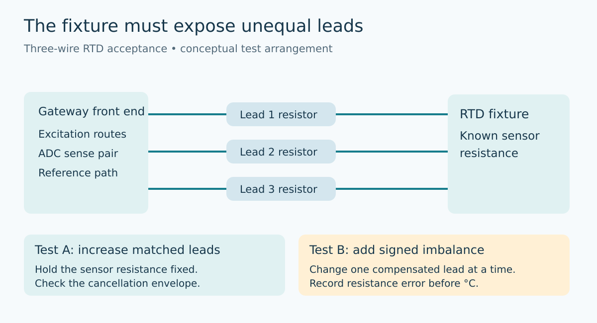
Start the project review with a drawing that names the current-carrying leads, sense connections, ADC input pair, reference resistor, and current-source assignments. Preserve those names in the firmware channel configuration and the test fixture. A generic connector label such as RTD_A does not reveal which conductor’s resistance is being compensated.
An integration drawing should also show the junction at the sensor. The test fixture must reproduce that junction rather than simply put three convenient resistors on three terminals. If the schematic and fixture use different interpretations of the third wire, agreement between the ADC and a resistor box can be misleading.
Separate absolute resistance from imbalance
Consider an illustrative Pt100 calculation near a region where a sensitivity of approximately 0.385 Ω per degree Celsius is appropriate. If a topology leaves 0.20 Ω of uncompensated lead imbalance, dividing 0.20 Ω by 0.385 Ω/°C gives roughly 0.52 °C. This is a local engineering estimate, not a full-range conversion equation or a measured result.
That example is useful because 0.20 Ω can look small on a cable drawing while being material in a temperature budget. It also shows why a statement about total cable resistance alone is incomplete. Two installations can have the same average lead resistance but different imbalance. Their residual errors need not be the same.
For full-range acceptance, use the project’s specified RTD characteristic and conversion method, not the local approximation above. Keep the sensor’s tolerance separate from acquisition electronics error. Otherwise a broad sensor tolerance can accidentally hide an input-channel defect, or an exceptionally accurate resistor fixture can create an unrealistic impression of installed temperature accuracy.
Design a fixture that perturbs one assumption at a time
Begin with a known resistance representing one temperature point and matched simulated leads. Verify the basic transfer function. Then increase the relevant lead resistances together while maintaining their match. This checks the intended cancellation over the declared cable range without simultaneously introducing an imbalance.
Next, hold the sensor resistance fixed and change one compensated lead at a time. Include both signs of imbalance. Record the resulting resistance estimate before converting it to temperature. Reversing the imbalance is particularly useful because it separates a systematic cable contribution from a fixed offset elsewhere in the channel.
Do not declare a universal acceptable mismatch from this article. Derive the allowable imbalance from the product’s allocated cable error, selected topology, and required temperature range. The fixture values should come from that requirement. If the planned cable and connector assembly cannot meet it, the useful outcome is a design change, not a looser spreadsheet label.
Excitation and settling need separate experiments
A cable-mismatch test does not characterize excitation-current mismatch. CN-0383 treats current matching as another contributor. For a production implementation, review the selected converter’s limits and the actual routing of its excitation currents. Determine whether a planned calibration or current-swapping method addresses the implemented circuit; do not assume that a technique from a different reference configuration transfers unchanged.
Similarly, a settled single-channel result does not validate a multiplexed scan. If the gateway switches channels, excitation routing, gain, or reference selection, specify when a conversion becomes eligible for use. Test the production scan sequence with channels at meaningfully different resistances. This is a separate acquisition test, not evidence that the cable compensation itself works.
Avoid collapsing these experiments into one final “temperature accuracy” number too early. A structured report preserves the input resistance, simulated leads, excitation configuration, sequence, and raw conversion. When a limit is missed, those records show which design assumption needs attention.
Decide when four wires are worth the connector cost
If the required cable assembly cannot maintain the balance the three-wire design needs, reconsider the architecture. Four-wire sensing can avoid the same first-order lead-drop problem by separating excitation and voltage sensing, but it requires another conductor and a compatible front end. It does not eliminate every error source or remove the need to check input and excitation constraints.
This is a product tradeoff rather than a marketing ranking. A three-wire channel can be the appropriate solution when the installation and error allocation support it. A four-wire channel can be justified when the connector, harness, and customer maintenance practices make it the more predictable choice. Document the decision against a measurable installation requirement.
Deliver the cable requirement with the board
For an Obeita custom acquisition gateway, the release package should identify the supported RTD connection, permitted lead conditions, applicable conversion range, calibration scope, and fixture wiring. Include unequal-lead results alongside precision-resistor results. An installer should be able to determine whether a replacement harness still satisfies the channel contract.
The goal is not to add paperwork to a temperature input. It is to keep a channel that works on a short bench connection from acquiring an unexplained installation-dependent offset. The tests above are proposals; this article reports no manufactured-board measurements, environmental qualification, or certification.
Source and topic provenance
Circuit-specific foundation: Analog Devices, CN-0383, Revision D, three-wire configuration and lead-resistance discussion, printed pages 9–11: Analog Devices CN-0383, Revision D, printed pages 9–11
Topic selection uses the preserved Google Trends RISING row “industrial iot solutions,+110%,” Worldwide, all categories, web search, July 19–October 19, 2026. The rising evidence applies to the parent topic, not to this title, RTDs, or any claimed sensor demand.