STM32H750 JPEG Decode Output: Convert MCU Blocks Before Treating Them as Display Pixels
A successful STM32H750 JPEG decode does not produce an ordinary RGB framebuffer. The codec emits minimum coded units, or MCUs, containing component blocks. Before displaying them, the application must interpret the color space and sampling factors, reorder the blocks, expand subsampled chroma and convert the result to the required pixel format.
This article follows the H750 YCbCr decoding path in AN4996 Rev 5, March 2026. DS12556 Rev 8 confirms the H750 JPEG codec and block-based YCbCr support in DMA2D. The register reference is RM0433 Rev 9, chapter 18. Here, MCU means a JPEG coding unit, not the microcontroller.
Identify the output grammar before copying bytes
For the YCbCr arrangements documented in AN4996, each component block contains 64 eight-bit samples. The sampling factor determines how those blocks form one MCU:
- 4:4:4: one Y block, one Cb block and one Cr block; 192 bytes covering 8 by 8 image pixels.
- 4:2:2: two Y blocks plus one Cb and one Cr block; 256 bytes covering 16 by 8 pixels.
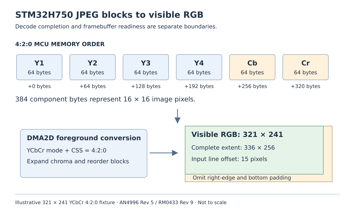
- 4:2:0: four Y blocks plus one Cb and one Cr block; 384 bytes covering 16 by 16 pixels.
In the 4:2:0 memory order, RM0433 Table 144 places Y1, Y2, Y3, Y4, Cb and Cr at successive 64-byte offsets. The chroma blocks serve the whole 16-by-16 region. They are not additional horizontal strips of visible pixels.
Derive the conversion configuration from the parsed image information. Do not assume that every asset exported by the same graphics tool retains the previous asset’s sampling factor. A byte copy that happens to resemble one image can scramble another without any JPEG-decode error.
Keep logical dimensions and complete-block dimensions
The codec outputs complete MCUs even when the image ends partway through a block. Edge MCUs include extra samples that must not become visible image area.
Consider a proposed 321-by-241-pixel YCbCr 4:2:0 fixture. Its complete-MCU extent is 336 by 256 pixels. It occupies 21 MCU columns and 16 MCU rows: 336 MCUs, or 129,024 decoded component bytes. These are layout calculations, not a compressed-file size estimate or a measured memory dump.
width = 321
height = 241
mcu_columns = (width + 15) // 16
mcu_rows = (height + 15) // 16
decoded_component_bytes = mcu_columns * mcu_rows * 384
Retain the original dimensions separately from the rounded extent. Allocating a component buffer by multiplying original width by height and a guessed RGB bytes-per-pixel value confuses two representations. Likewise, overwriting the logical dimensions with rounded values can cause padding to become visible later.
Configure the YCbCr conversion path explicitly
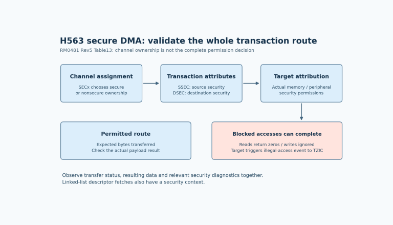
On H750, DMA2D’s foreground path supports the documented YCbCr block conversion and chroma upsampling. AN4996 section 4.1.1 specifies foreground color mode CM = 0b1011 and sampling selection CSS = 0b10 for 4:2:0. The background path does not provide the same YCbCr capability.
For the illustrative width, the foreground input line offset is 336 - 321 = 15 pixels. Preserve pixel offset mode when applying that formula: RM0433 defines the LOM selection and distinguishes pixel offsets from byte offsets. Do not multiply 15 by the eventual RGB output pixel size and write that value as a pixel offset.
Set the transfer’s visible width and height to 321 and 241, and configure the output format and output line offset for the actual destination. The foreground line offset skips right-edge padding; it does not by itself limit the number of output rows. Limiting the transfer height excludes the padded bottom region.
RM0433 also rejects YCbCr in plain memory-to-memory mode and requires the transferred pixel count plus foreground line offset to satisfy the sampling alignment. Here, 321 + 15 = 336 satisfies the 16-pixel condition. Use the documented conversion mode rather than treating the block buffer as an already converted raster.
Preserve block position across output chunks
If conversion starts before the full image is decoded, every chunk needs both valid component bytes and the correct position within the image. A DMA callback’s arbitrary byte count is not automatically a complete set of coding units.
AN4996 recommends output chunks that are multiples of 768 bytes when supporting its different color spaces and sampling factors. For the chosen 4:2:0 case, 768 bytes contain two complete MCUs. This alignment helps preserve coding units; it does not make every chunk an entire image row. A row in the proposed fixture contains 21 MCUs, so two-MCU chunks can cross its boundary.
Maintain the conversion position and input ownership accordingly. Release a chunk for reuse only after its consumer has finished. Handle the final valid byte count explicitly rather than converting the unused capacity of the last buffer.
Test boundaries that a uniform picture conceals
Prepare distinct left/right colors, marked corners and an odd-sized image. Compare a known decoded reference with the converted output, checking the first pixel after each MCU boundary, the last visible column and the last visible row. Repeat with 4:4:4 and 4:2:2 assets only after reconfiguring their different block geometry.
No decode, display or speed benchmark was executed here. Grayscale and CMYK require their documented software conversion path rather than this YCbCr DMA2D recipe. The acceptance result is a correct representation transition: component blocks become a bounded RGB image with the original dimensions, not merely a completed JPEG operation.