Six-Wire Bridge Inputs: Sense the Excitation at the Load Cell, Not the Gateway
A bridge sensor described as 2 mV/V does not promise the same output voltage for every cable assembly. The ratio refers to the excitation actually applied to the bridge. If an acquisition gateway uses its local excitation supply as the ADC reference while the bridge sits beyond resistive power leads, the system can retain a cable-dependent scale error despite being called ratiometric.
The practical distinction is between a shared source and a shared voltage. A six-wire connection can bring the bridge-end excitation back to the reference input on separate sense conductors. That changes which physical voltage defines the measurement scale; it is not simply a more elaborate connector.
Identify all three conductor pairs
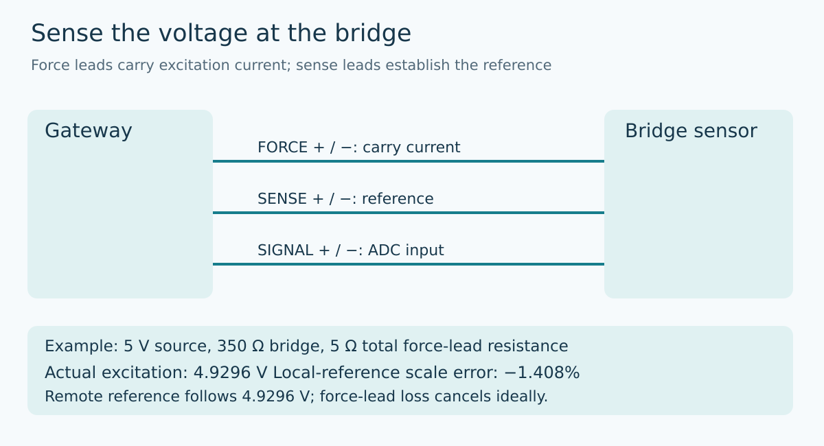
A conventional six-wire bridge arrangement has an excitation pair, a signal pair, and a sense pair. The excitation or force pair delivers current. The signal pair carries the small differential bridge output. The sense pair observes the excitation at the sensor and can establish the ADC’s differential reference.
Texas Instruments’ SBAA532A, sections 3.2 and 3.3, contrasts four-wire and six-wire arrangements. In the four-wire example, excitation-lead resistance reduces the voltage across the bridge relative to the reference at the source. In the six-wire example, the reference is taken from the bridge through the additional sense connections.
Do not confuse a sense conductor with a shield or an extra signal return. Nor should the drawing imply that the two signal leads supply the reference. Name the six terminals explicitly and preserve the sensor manufacturer’s polarity convention in the gateway harness drawing. A connector whose labels are clear only to the original designer is a maintenance risk.
Follow the voltage drop through a concrete example
Consider a deliberately simplified bridge whose excitation-port resistance is 350 Ω, driven from a 5 V source through 5 Ω total force-lead resistance. Assume the resistance values are fixed, the source is ideal, and the bridge’s specified full-scale sensitivity is 2 mV/V. These are illustrative values, not measurements or specifications of a particular product.
The excitation current is 5 V divided by 355 Ω, or approximately 14.0845 mA. The bridge receives 4.92958 V. At the assumed full-scale load, its differential signal is therefore 9.85915 mV, not 10 mV.
If the ADC reference remains 5 V at the gateway, the input-to-reference ratio is approximately 0.00197183. Compared with the intended ratio of 0.002, the scale is low by 1.40845%. This is a multiplicative effect; subtracting a zero-load offset does not correct it.
With an ideal bridge-end reference of 4.92958 V, the ratio becomes 9.85915 mV divided by 4.92958 V, or 0.002. The force-lead voltage loss cancels in that ideal ratio. The calculation explains the purpose of the sense pair without claiming that a real channel has zero error.
Remote sensing is not necessarily remote regulation
In this arrangement, the sense leads inform the ADC reference. They do not necessarily command the excitation supply to increase its output. The bridge can still operate at a lower voltage than the source. Its output amplitude, available signal-to-noise performance, and compliance with the sensor’s allowed excitation range still need consideration.
A remotely regulated excitation source is another architecture: it uses feedback to control the voltage at the remote load. Do not silently treat that as equivalent to feeding a converter’s reference inputs. A schematic and specification should say which function exists. The presence of terminals labeled SENSE does not, by itself, establish a regulation loop.
This distinction matters when a customer expects a nominal excitation value at a long cable’s far end. Ratiometric acquisition can preserve the ideal scale while leaving the actual bridge voltage below that value. The ratio and the voltage requirement are separate acceptance questions.
The reference input is a real electrical load
The ideal cancellation assumed negligible sense-path voltage drop. Real reference inputs draw current, and some have dynamic loading. Any input current flowing through sense-lead or filter resistance creates an additional difference between the bridge-end voltage and the reference actually seen by the converter.
Use the selected ADC’s reference-input requirements, allowable differential reference range, common-mode limits, and recommended drive network. A sense wire does not grant permission to exceed those limits. If the design adds buffers or filtering, account for their offset, loading, and settling rather than assuming that the word “Kelvin” removes those errors.
The same discipline applies to the signal path. Its small input currents usually create much less lead drop than the excitation current, as SBAA532A explains, but “much less” is not identical to zero. The required precision and actual component limits decide whether that residual matters.
Four-wire sensors need an explicit fallback
Some installations provide only excitation and signal pairs. A six-terminal gateway cannot remotely sense a voltage for which no conductors exist. Locally connecting sense to excitation may allow a supported four-wire configuration, but it restores the source-end reference and its cable-drop sensitivity. Follow the selected front end’s documented wiring rather than leaving unused reference inputs floating.
If calibration includes the installed cable, preserve that scope. Replacing the cable, changing connector resistance, or changing the excitation-port resistance can invalidate the compensation implicit in a gain adjustment. A calibration record that lists only the board serial number misses the physical elements that set this error.
For a design review, calculate both ratios using the maximum intended force-lead resistance and the actual sensor excitation model. Then confirm whether the reference is taken at the bridge or at the gateway. This narrowly targeted check is more informative than asking whether the channel is “ratiometric” in general.
Source and topic provenance
Texas Instruments, A Basic Guide to Bridge Measurements, SBAA532A, March 2024 revision, sections 3.2–3.3 supplies the four-wire and six-wire circuit foundation. The numerical harness example and integration recommendations above are original analytical examples, not measured acceptance results.
The preserved Google Trends RISING row “industrial iot solutions,+110%,” worldwide, all categories, web search, July 19–October 19, 2026 supports the parent industrial-integration topic. It does not claim rising search interest specifically in load cells, six-wire bridges, or this title.