Reviewing AI-Assisted Device-Tree Changes: From Boot Logs to Real Peripherals
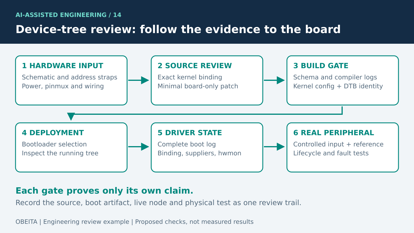
An AI-assisted device-tree change is a hardware-description proposal. A successful compile means the source can be translated; it does not establish that the bootloader loaded that tree, that the right driver bound, or that the peripheral behaves correctly. Review must connect the generated diff to the board schematic, the running kernel and an observable peripheral transaction.
The following TMP102 example uses a hypothetical board and constructed generated-style snippets. No AI tool execution, board boot or sensor measurement is claimed. The corrected fragment is incomplete by design and is not a drop-in board description.
1. Give the drafting assistant the board’s evidence
Provide the exact board and assembly revisions, SoC, kernel commit, vendor patches, existing DTS/DTSI include chain and bootloader selection mechanism. Include the schematic pages showing the bus, address straps, power rail, pull-ups and optional interrupt. Also supply the binding and driver from the kernel tree actually being built. Upstream documentation can guide review, but a vendor kernel may differ.
For this teaching example, assume the schematic places a TMP102 on the controller labelled i2c2, straps its seven-bit address to 0x48, connects the sensor to a named supply, and leaves ALERT unconnected. Assume the reviewed initial bus rate is 100 kHz. Those are explicit scenario inputs, not properties inferred from an existing Obeita board.
Ask for the smallest patch to the board file, an explanation of every added property, a list of dependencies and a verification plan. Prohibit invented pinctrl groups, GPIO numbers and compatible strings. If the included SoC tree already defines controller clocks or resets, the draft should preserve that arrangement rather than duplicate it from an unrelated example.
2. Identify why a plausible draft is still wrong
/* Deliberately flawed draft for an illustrative board. */
&i2c2 {
    status = "okay";
    clock-frequency = <1000000>;
    sensor@90 {
        compatible = "ti,tmp102";
        reg = <0x90>;
        interrupt-parent = <&gpio1>;
        interrupts = <7 2>;
    };
};
The address is a classic representation error: 0x90 corresponds to a write address byte for seven-bit address 0x48, but the child’s reg property should use the address representation required by its bus binding. Copying a datasheet transaction byte into the node silently describes another address. The unit address and reg agree with each other, so that agreement alone is weak evidence.
The 1 MHz bus rate is unsupported by the supplied project inputs. The interrupt properties were guessed despite ALERT being unconnected. The numeric interrupt flags also obscure their meaning and may belong to a different interrupt-controller binding. Missing pinctrl and supply information can be equally important, although some boards legitimately inherit their settings elsewhere. The reviewer must inspect the include chain before declaring any property universally mandatory.
The upstream TMP102 binding provides a concrete source for the compatible string, reg property, optional interrupt, label and vcc-supply. It does not tell us this board’s wiring. That distinction prevents a syntactically polished AI answer from becoming an invented schematic.
3. Review a minimal corrected fragment
/* Partial teaching patch. Labels must exist in the board tree. */
&i2c2 {
    pinctrl-names = "default";
    pinctrl-0 = <&i2c2_board_pins>;
    clock-frequency = <100000>;
    status = "okay";

    temperature-sensor@48 {
        compatible = "ti,tmp102";
        reg = <0x48>;
        vcc-supply = <&sensor_vcc>;
        label = "board-ambient";
    };
};
This fragment follows the stated scenario: a seven-bit address, a deliberately selected initial bus rate, a supply reference and no fictional interrupt. The pinctrl and regulator labels are placeholders for existing, reviewed board definitions. Before use, confirm their electrical voltage, ownership, enable polarity and sequencing. If those definitions do not exist, adding them requires a separate hardware-backed change.
A correction can also be smaller than this fragment. If the existing board include already supplies the correct pinctrl state or clock-frequency, retaining it may be preferable. Avoid an AI-generated cleanup that reorganizes unrelated controllers, changes shared supplies or introduces overlays merely to enable one sensor. A focused diff makes cause and effect easier to establish.
4. Validate against the selected kernel, then the selected boot artifact
Run schema validation in the actual kernel tree. The kernel’s binding validation guide distinguishes dt_binding_check for schemas from dtbs_check for device trees, and notes that invalid schemas can be skipped by dtbs_check. If a binding changes, validate it as well. Keep complete logs and separate new failures from pre-existing ones.
# Proposed checks in the exact configured kernel source tree:
make ARCH=<target-arch> CROSS_COMPILE=<tool-prefix> dtbs_check   DT_SCHEMA_FILES=hwmon/ti,tmp102.yaml

# On a target that exposes its live tree, with appropriate access:
dtc -I fs -O dts /sys/firmware/devicetree/base > running.dts
# Review the actual controller path, compatible, reg and supply.
# Discover the matching hwmon device; do not assume hwmon0.
The commands are proposed steps, not an execution transcript. Replace architecture and toolchain placeholders with the project values. A schema-filtered pass is useful during review, but it does not validate every interaction in a board tree. Follow it with the project’s broader DT checks and build requirements. Retain the kernel configuration that enables the controller and sensor drivers.
Record the built DTB filename and hash, image packaging step, bootloader configuration and deployed storage location. On the target, inspect the live tree’s relevant properties. Do not assume the source filename proves what booted, and do not demand an identical live-tree hash when the bootloader legitimately changes properties. Explain expected modifications and compare the hardware nodes that matter.
5. Use boot logs to locate the failure layer
Collect a complete serial boot log before filtering. Confirm kernel identity, board identity, controller registration, driver availability and any regulator or pinctrl errors. A deferred probe can indicate a supplier that is not ready; it is not automatically a defective compatible string. The kernel driver-model documentation describes deferred probing when a required resource is unavailable.
Do not require a particular success message: a healthy driver may be quiet. Inspect the relevant device-to-driver binding and locate the matching hwmon instance by its name and device relationship. Numeric adapter and hwmon indexes can change. The TMP102 driver documentation identifies the temperature input and other exported attributes. Confirm units through the applicable interface documentation before interpreting values.
6. Verify the real peripheral, including negative behavior
- Identity and path: show that the running node, physical bus and bound driver refer to the intended sensor. A directory appearing in sysfs is insufficient evidence of useful measurements.
- Controlled input: compare readings with an appropriate independent reference under stable conditions, then apply a safe, controlled temperature change. Define tolerance and settling time from the project requirements and sensor specifications before testing.
- Electrical behavior: if communication fails, inspect rail voltage, reset or enable behavior where applicable, and bus waveforms with suitable equipment. A logic capture should establish address, ACK behavior and timing; it cannot alone prove measurement accuracy.
- Lifecycle: propose repeated cold boots, warm reboots and supported suspend/resume cycles. Record whether the sensor is discovered consistently and recovers within the agreed time.
- Fault handling: on a safe test fixture, simulate unavailable power or a missing sensor. Acceptance should require a visible error and recovery policy, rather than a cached plausible value presented as fresh data.
Avoid indiscriminate bus scans on unknown hardware, and avoid raw I2C transactions that compete with a bound kernel driver. Use the established driver interface and a controlled diagnostic procedure. Keep the baseline DTB and a documented recovery path available before boot experiments.
7. What the final review should contain
Deliver the small DTS diff, schematic-to-property mapping, exact build inputs, validation logs, deployment identity, full boot log and peripheral test evidence. Mark every proposed test as pending until it has actually run. Agreement between two AI drafts is not substitute evidence for wiring or operation.
Obeita’s firmware and BSP diagnostics service is relevant to this bring-up workflow. The RK3566 embedded-terminal project provides related BSP and peripheral-integration context; it is not evidence that this hypothetical TMP102 patch was part of that project.