STM32H750 USB High Speed: Budget the External ULPI PHY Before Routing
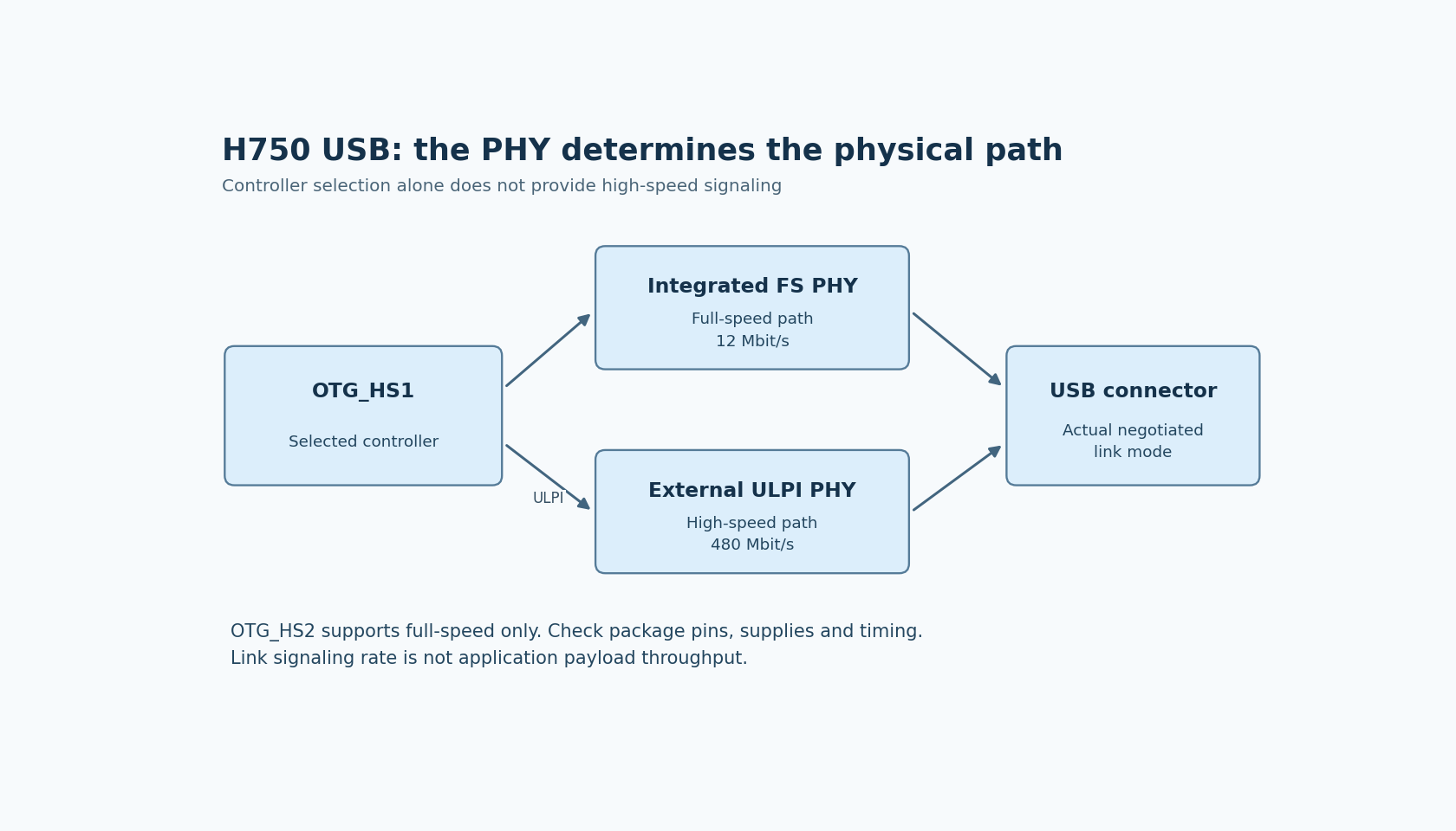
Selecting the STM32H750 USB high-speed controller does not create a 480 Mbit/s physical connection through its integrated full-speed transceiver. A high-speed design needs the supported controller path, an external ULPI PHY and a board that implements the PHY's required signals, supplies and timing.
DS12556 Rev 8, section 3.41 states the distinction explicitly: OTG_HS1 supports high-speed operation with an external ULPI PHY, while the integrated transceivers support full-speed operation at 12 Mbit/s. It also identifies OTG_HS2 as full-speed only. Controller naming is therefore insufficient evidence for the physical link speed.
Trace the path from endpoint logic to the connector
Draw the selected controller, its MCU-to-PHY interface, the PHY and the connector as separate blocks. Label where the external PHY is actually present. A direct D+/D− connection using an integrated full-speed transceiver is a different path from ULPI high-speed operation.
This distinction matters early in board selection. A development board can expose a convenient USB connector without implementing the external PHY path that a high-throughput product requires. Verify its schematic instead of inferring capability from the MCU's headline feature list.
It also matters when reviewing middleware. Endpoint and class configuration operate above the physical implementation. Selecting a high-speed-oriented software instance does not supply missing PHY hardware or route an unconnected ULPI signal.
Budget the ULPI connection as a real peripheral bus
The H750 datasheet describes a 12-signal ULPI connection and its 60 MHz clock relationship. Include the data, control and clock signals in the pin-allocation review for the exact MCU package and PHY.
Check alternate-function conflicts against the rest of the board. A design that already uses those pins for another mandatory interface may require a different allocation or package. Do not postpone this issue until after USB firmware is available.
Use the PHY datasheet and the MCU's ULPI timing tables together for the electrical design. Clock direction, setup/hold requirements, voltage compatibility and routing constraints are properties of the selected connection, not details inferred from the 480 Mbit/s number at the USB connector.
The USB controller description in RM0433 Rev 9 is the corresponding programming reference. Review interface selection and controller initialization only after the physical path is identified.
Distinguish MCU USB power from external-PHY power
The MCU's USB-related supply pins and regulator choices depend on package availability and the supported supply configuration. AN4938 Rev 7, section 2.1.2 describes these cases across its covered H7 devices; the H750 datasheet supplies the applicable details for the chosen part.
The external PHY has its own supply and sequencing requirements. A correct MCU USB supply does not establish that the PHY is powered, released from reset or presenting a valid interface clock.
Keep those checks separate in the bring-up record. Likewise, the presence of VBUS at a connector is not proof that every internal and external supply involved in the chosen path is valid. Use the actual schematic and component specifications rather than a generic USB wiring diagram.
No power or signal measurements were performed for this article, and no universal PHY supply circuit is proposed.
Verify the negotiated link before measuring payload throughput
Once the board and firmware are ready, establish the actual negotiated USB speed using suitable host/controller observations. Successful enumeration alone does not establish that the link is operating at high speed.
Only then evaluate application throughput with a defined transfer type, endpoint configuration and payload workload. The 480 Mbit/s figure is a link signaling rate, not a promise of equivalent application bytes per second. Protocol overhead, host scheduling, software and memory movement affect the achieved result.
If a transfer is slower than expected, preserve both observations: negotiated speed and application rate. A full-speed physical path requires a different diagnosis from a verified high-speed link whose application cannot keep the transfer pipeline supplied.
Make the hardware requirement explicit at design approval
A useful approval record names the MCU ordering code and controller, external PHY part, ULPI pin map, clock relationship, supply arrangement and connector implementation. It then identifies the evidence still required for electrical compliance and throughput qualification.
For a product that only needs full-speed operation, the simpler integrated-transceiver path may be appropriate. For a product requiring high-speed operation, the external PHY is part of the board architecture and bill of materials, not a firmware enhancement to add later.
No USB enumeration, compliance test or performance benchmark was run here. The engineering decision is whether the designed physical path can support the required link mode before software throughput becomes the question.