STM32G474 HRTIM Fault Shutdown: Trace the Entire Output Protection Path
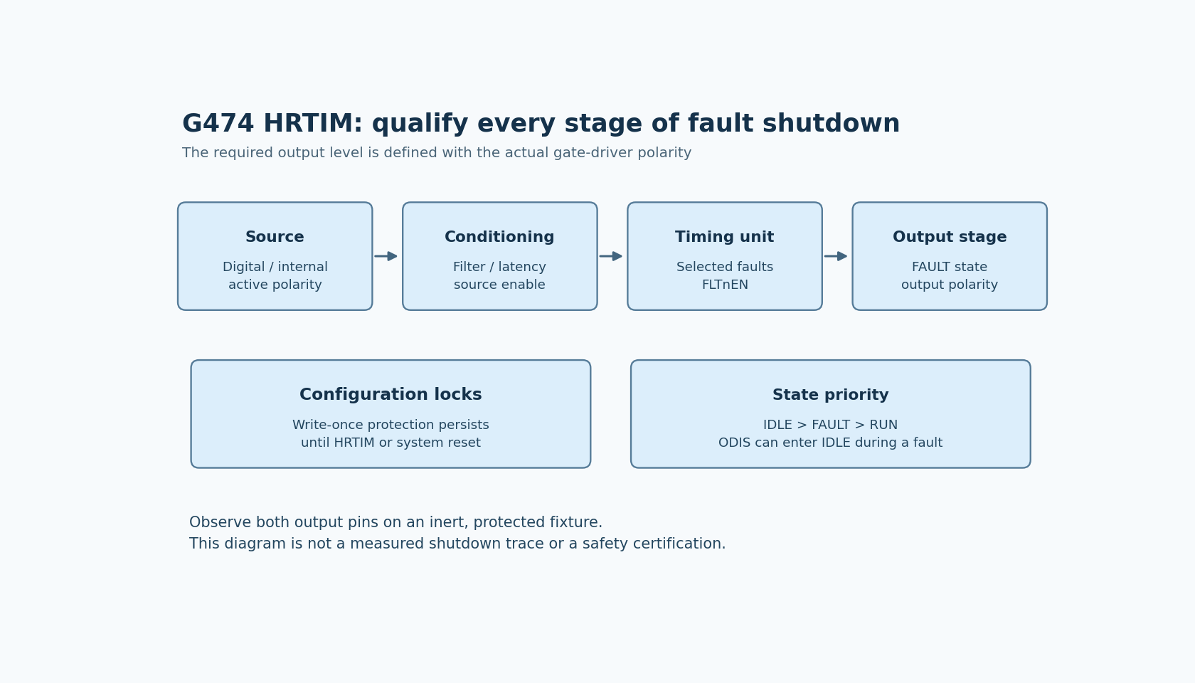
A fault flag in firmware does not establish that both STM32G474 HRTIM outputs reached the gate-driver state intended by the board designer. The protection path includes source selection, signal conditioning, timer-level enables and output-level fault behavior. A mistake at any stage can invalidate the intended shutdown.
RM0440 Rev 9, section 28.3.17 describes that chain. AN4539 Rev 5, section 4 gives a concrete complementary-output example with deadtime and fault shutdown. Its board and pin assignments are examples, not instructions to energize an arbitrary power stage.
Define the electrical result first
Write down the required state of each HRTIM pin and the corresponding gate-driver output. Include driver polarity and enable behavior. “Inactive” at the timer is a logical configuration choice; the board's safe electrical state depends on the complete path after that pin.
In the cookbook's example, the two complementary outputs are forced low using positive output polarity and an inactive fault state. That combination explains the result. Copying only the inactive-state setting while changing polarity or external circuitry is not an equivalent design.
Deadtime and fault shutdown also answer different questions. Deadtime separates complementary switching transitions in normal operation. The fault path determines what happens when the protection condition is asserted. Both need a defined relationship to the actual driver.
Follow the selected fault through the registers
The reference manual describes fault sources that can originate from a digital input or supported internal signals. For the chosen fault channel, identify the source and active polarity before considering the output response.
Next inspect filtering. With the fault filter field set to zero, the manual describes an unfiltered asynchronous path independent of the HRTIM clock. Nonzero settings use digital filtering that requires a specified number of valid samples and therefore adds latency. A shorter pulse can be discarded before becoming a qualified fault.
That is a genuine design tradeoff, not a recommendation to disable every filter. The conditioning must reject the disturbances the product intends to ignore while still admitting the fault pulse widths it must detect. Derive a latency budget using the selected clock and filter values; do not substitute the timer's advertised resolution for shutdown latency.
Then check the timer's fault-source enables and the fault-state fields for both outputs. A configured fault input is not sufficient if the relevant timing unit does not use it or an output is not configured to respond as intended.
Treat recovery as a separate state transition
For the normal return-to-RUN path, the manual describes a fault state that requires software re-enabling; a still-active fault takes priority over RUN. Read that overview together with the output state machine on page 953: IDLE has higher priority than FAULT, and setting ODIS can move an output from FAULT to IDLE even while the fault remains asserted.
Consequently, configure and qualify the IDLE output level as well as the FAULT level. A persistent fault is not a guarantee that the pin retains one electrical level through every software-requested state change.
Build the recovery policy around that behavior. Clearing a diagnostic flag, deasserting an external signal and re-enabling outputs are not interchangeable steps. A product may require additional checks before rearming, depending on its power-stage and system requirements.
The cookbook demonstration uses a user button to rearm its example. That is a demonstration policy, not a general recovery requirement. The production policy should identify who authorizes a restart and which conditions must be established first.
Apply configuration locks deliberately
RM0440 describes write-once locks for fault conditioning and for timer fault-source selection. Once enabled, the protected configuration remains frozen until the relevant HRTIM or system reset.
This helps prevent later software from casually changing the protection setup, but it also affects initialization and diagnostics. Complete the intended configuration before locking it. A debugger write that appears ineffective after locking is not evidence of a broken register interface.
Document the reset needed to change the locked configuration. A development workaround that repeatedly resets the device should not become an unexplained production recovery sequence.
Qualify the chain without improvising a power fault
Begin with a protected, inert setup that does not energize the power stage. Verify the configured source, active level, filtering, both output pin states and the rearm sequence using suitable observation equipment. These are proposed checks; no G474 board or waveform was tested for this article.
Include a fault present before outputs are enabled, a fault asserted during ordinary operation and a fault held through an attempted rearm. Add pulse-width cases derived from the selected filter, within the approved fixture's limits. Observe the actual output pins rather than relying solely on an interrupt or status flag.
Electrical propagation through the driver and power stage requires its own qualified evidence. The register analysis does not establish a certified safety function or a complete system reaction time. Its practical contribution is a traceable protection chain: every stage has an intended configuration, an expected output and a specific observation that can confirm it.