TSS721A M-Bus Interfaces: Separate Bus Power from Reply-Current Modulation
A wired M-Bus meter can receive a request correctly yet fail to return a usable response. That asymmetry matters: the two directions do not use the same electrical mechanism. A gateway integration that treats the cable as a conventional differential serial pair can miss both the reply-current path and the load that the meter presents while it is silent.
The concrete interface examined here is Texas Instruments TSS721A, datasheet SLAS222B, revised November 2010. This is the wired Meter-Bus slave transceiver, not a wireless M-Bus radio and not an RS-485 transceiver. The discussion develops a design-review and proposed measurement plan; it does not report a built circuit, field measurements, or protocol certification.
One cable, two modulation directions
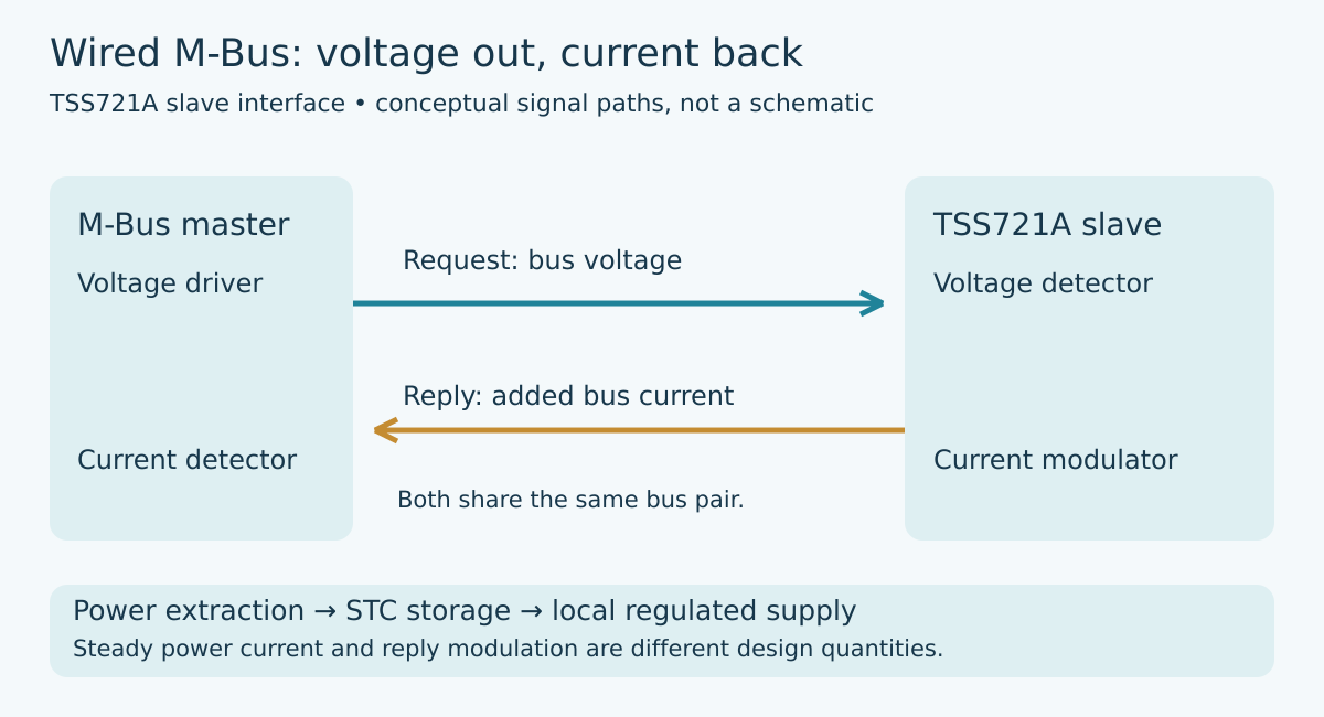
For master-to-slave transfer, the TSS721A detects changes in bus voltage using a dynamically established reference. For slave-to-master transfer, it changes the current drawn from the bus. The master must detect that change. The transceiver also derives power from the bus, so its steady load and its intentional reply modulation have different jobs even though both appear in the same current measurement.
This distinction gives a useful first fault split. If the meter recognizes incoming requests, the voltage-detection path is doing at least part of its job. That result does not establish that the outgoing current modulation reaches the master with the required amplitude and shape. Conversely, seeing reply-shaped activity at a local logic pin does not prove that the bus current is changing correctly.
Draw three paths in the review: incoming voltage detection, outgoing current modulation, and power extraction. Label the physical bus terminals separately from the local logic signals. This prevents a successful UART loopback from being mistaken for an electrical M-Bus interface test.
Read signal directions from the device, not from habit
The TSS721A pin names deserve particular care. Its terminal table identifies TX and TXI as data outputs and RX and RXI as data inputs. Those directions describe the transceiver. They are not an instruction to connect similarly named MCU pins together. Confirm the selected polarity and trace the information flow on the schematic before checking firmware’s UART assignment.
For example, label a net “MCU receives decoded bus data” rather than relying only on “TX.” Label the outgoing net “MCU drives reply modulation.” Such functional names remain useful when an inverted signal variant is selected or an isolation stage is added. Verify the logic-level interface and unused input treatment against the actual circuit recommendations; the existence of both polarity variants does not mean every combination can be connected arbitrarily.
The datasheet also describes local echo of current modulation on the receive outputs. Therefore, reception of the meter’s own transmitted byte is not, by itself, proof of an unexpected second sender. Preserve whether a trace was captured during transmission or while awaiting another station. Otherwise an expected electrical echo can become a misleading software collision report.
Do not spend the reply current as an ordinary power budget
The TSS721A uses separate programming resistors for its bus-powered supply current and its modulation current. Review them as different design choices. Increasing the ordinary load to support more electronics is not equivalent to establishing the intended reply amplitude. Similarly, a correct modulation resistor cannot compensate for an overloaded local supply.
An illustrative aggregate calculation makes the distinction visible. Suppose a hypothetical master segment has 24 slaves whose documented worst-case idle allocations are each 1.5 mA. Their combined baseline is 36 mA. Suppose the active reply adds a hypothetical 12 mA. The master then sees 48 mA during that reply state, before other loads or tolerances. The relevant change for reception is 12 mA, not the full 48 mA.
These numbers are deliberately chosen arithmetic, not a TSS721A compliance limit or a recommended master rating. The actual design must use the selected slave circuits, device tolerances, permitted number of simultaneous transmitters, cable network, and master specifications. They explain why checking only the total supply-current capacity is insufficient: power delivery and demodulation sensitivity are separate acceptance questions.
Local energy storage is part of the power path
The TSS721A charges a support capacitor at STC and regulates the local supply. Its datasheet explains how that storage supports a delayed supply shutdown when the bus fails. Treat the energy reserve as part of a complete operating envelope, not as unlimited permission for the attached microcontroller to draw bursts.
List the meter electronics’ operating modes and their current requirements. Include acquisition, computation, communication, and any planned data-saving activity. Then compare them with the available supply and storage behavior using the datasheet’s limits and equations. A subsystem that behaves on an independent laboratory supply may not behave identically when transferred to the bus-derived rail.
If a proposed experiment intentionally removes bus power, distinguish loss detection from time available to finish a write. Capture the relevant local supply and power-fail indication; do not infer the reserve from the capacitor’s nominal value alone. Tolerance, load, thresholds, and the selected circuit all matter. Avoid adding a nonvolatile write merely to demonstrate recovery if the application has no requirement for one.
Observe the bus where the master makes its decision
A useful commissioning capture combines the request voltage waveform, the reply-current waveform, and local logic activity under one time reference. Follow the approved equipment and measurement-isolation procedures. The objective is to establish where a correctly timed local response stops being a distinguishable bus response, not to modify a live metering installation casually.
Start with one known slave and the intended master. Add the planned cable and additional idle loads in controlled steps within the equipment ratings. At each step, distinguish a change in baseline current from a change in reply modulation. Record the circuit revision, programming resistors, supply conditions, and UART configuration with the capture so that a later resistor or firmware change does not invalidate the comparison silently.
The final gateway integration record should show which device detects bus voltage, which device creates and senses reply current, and which circuit powers the slave electronics. When those roles are explicit, a one-way communication failure becomes a bounded electrical investigation rather than another reason to increase serial retries.