STM32G431 SMBus PEC: Count the Trailer and Leave Reload Mode for the Final Segment
Enabling hardware packet error checking does not make an ordinary data count automatically include a checksum trailer. On STM32G431, the I2C byte counter and final-segment state determine whether the peripheral actually transfers the PEC byte. A request left in reload mode does not reach the same operation.
This example uses I2C1 as a single controller transmitting two data bytes followed by one hardware-generated PEC. DS12589 Rev 6, section 3.28 and Table 8 confirms SMBus/PMBus hardware support on the G431’s three I2C instances. No fourth instance is inferred from the wider family manual.
Separate CRC coverage from the transfer count
RM0440 Rev 9, sections 39.4.11 and 39.4.12 describes a CRC-8 PEC covering message bytes, including addresses and their read/write bits. That coverage is different from the application bytes counted in the current data segment.
For the example, the address participates in the checksum calculation but is not an additional application-data byte to add to NBYTES. The two data bytes and the trailing PEC occupy three counted byte positions. With a PEC requested on the final segment, the payload count is NBYTES - 1.
Configure I2C_CR1.PECEN before enabling I2C; the manual prohibits changing that configuration while the peripheral is enabled. Treat this as part of the driver’s initialization contract, not an extra bit to toggle casually in an active transaction.
Walk the two-write, three-byte sequence
Section 39.4.15 and Figure 562 give the controller-transmit example. The following is a paper state description, not an executable register recipe:
Payload bytes to supply: 2
NBYTES = 3
RELOAD = 0
PECBYTE = 1
AUTOEND = 1
Expected software TXIS services: 2
Final counted byte: PEC generated by hardware
The driver programs the target address and transfer configuration before requesting START. It supplies the first and second data bytes in response to the transmit requests. Hardware then sends the PEC; automatic-end mode follows it with STOP.
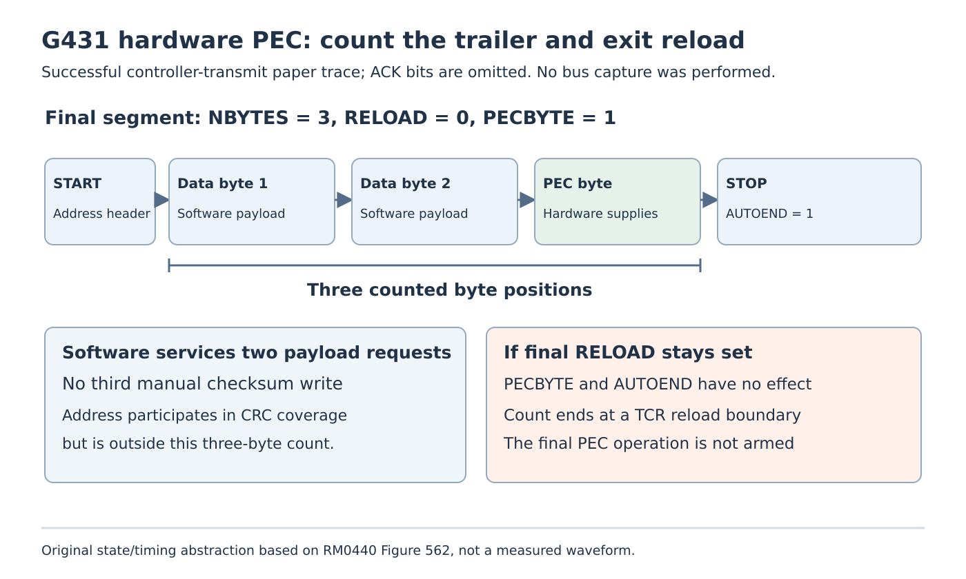
Do not add a third software write containing a manually calculated checksum to this hardware-generated path. That would give software responsibility for a position that the selected peripheral sequence already owns. The driver must distinguish its payload-buffer length from the hardware’s inclusive transfer count.
As a contrasting paper case, NBYTES = 2 with the same final PEC request allocates only one payload position before the PEC. It does not describe two payload bytes plus an uncounted trailer. Fixing the polynomial or checksum seed cannot repair that byte-boundary mismatch.
End reload mode before requesting the terminal operation
PECBYTE has no effect while RELOAD is set. A chunked driver therefore needs an explicit transition for its final segment. The final count includes the remaining payload and PEC, and the final segment clears RELOAD while requesting PEC transfer.
If RELOAD remains set, reaching the programmed count instead produces the reload boundary, TCR, with clock stretching. AUTOEND also has no effect in that state. Merely setting PECBYTE in a common per-chunk configuration does not convert the last ordinary chunk into a PEC-terminated message.
Review the driver’s state machine at the transition from intermediate to final segment. Record who owns NBYTES, RELOAD and PECBYTE, and when the update is legal. The register description prohibits changing NBYTES while START is set. Avoid a generic read-modify-write suggestion that ignores the driver’s interrupt or DMA ownership.
Choose the boundary after PEC deliberately
For the final segment, AUTOEND = 1 gives the documented automatic STOP. With AUTOEND = 0, the controller transmits PEC and then raises TC, holding the clock low until software requests the next operation. Figure 562 shows software programming a repeated START at that point.
Those alternatives do not define every possible combined SMBus message or its checksum lifetime. Derive any longer command sequence from the inspected peripheral behavior and the target’s protocol. Do not assume a generic repeated-start tutorial has already selected the right PEC scope.
DMA also preserves a useful asymmetry. Section 39.7 says transmit DMA supplies data while PEC transfer is managed by the peripheral counter. Receive DMA transfers include the received PEC. Hardware checking therefore does not justify assuming that every receive buffer silently excludes its trailer.
Diagnose the requested check before trusting its absence of errors
In controller reception, a correctly armed final PEC position is compared with the calculated value; mismatch raises PECERR. An absent error flag alone does not prove that the intended byte was ever selected for checking. Preserve the count, reload state, PEC request and actual trailer boundary with the error result.
Before target qualification, review ES0431 Rev 9 for the actual silicon. Its I2C limitations include setup-time sampling, spurious controller bus-error reporting and a first-byte transmission stall under particular clock-ratio and service-timing conditions. A corrected PEC count does not remove those independent constraints.
No bus traffic or checksum execution was performed here. A later isolated fixture should compare the two-payload-byte case with the wrong-count and final-reload cases, capturing the counted boundary and software service count. The immediate deliverable is the paper trace: two payload writes, three counted bytes, and a final state that actually permits hardware PEC.